38
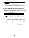
II Warning
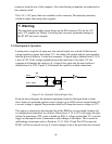
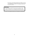
Do not exceed the min/max voltage specification fed into the digital input
lines. The absolute minimum voltage is –0.1V and the absolute maximum
voltage is 5.2V. Exceeding the above specifications will damage the PC62C.
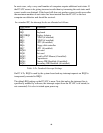
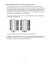
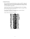
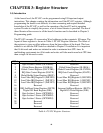
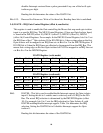
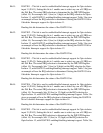
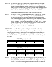
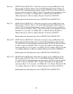
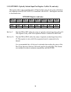
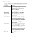
3.11) OPTORD1 - Optically Isolated Input Port Register 1 (offset 22, read only)
The register allows one to read the status of Opto Isolator 16 to 31. It is only valid when
the expansion board (PC62C-EXP16) is connected to the PC62C. The Register structure
is described below.
OPTORD1 Register (read only)
Bit 15 Bit 14 Bit 13 Bit 12 Bit 11 Bit 10 Bit 9 Bit 8
PC15 PC14 PC13 PC12 PC11 PC10 PC9 PC8
Bit 7 Bit 6 Bit 5 Bit 4 Bit 3 Bit 2 Bit 1 Bit 0
PC7 PC6 PC5 PC4 PC3 PC2 PC1 PC0
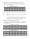
Bit 0 to 7: The bits PC0 to PC7 reflect the status of optically isolated input lines 15 to 23.
This register is only valid if the expansion board is connected to the PC62C
Bit 8 to 15: The bits PC8 to PC15 reflect the status of optically isolated input lines 24 to 31.
This register is only valid if the expansion board is connected to the PC62C.
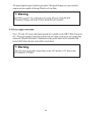
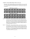
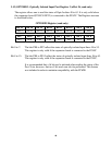
It is recommended that a 16 bit read is initiated when reading the status of the
Port. Note, however, that two 8 bit reads can also be performed. This feature
was included in order to maintain compatibility with the PC62B.