


WATLOW Series 988 User’s Manual 7.3
Tuning, Manual Operation, Alarms and Error Codes, Chapter 7
Tuning
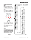
1. Apply power to the Series 988 and enter a set point. Begin with
[``Pb] set to [```1]; [``rE] or [``It] set to [`0)0]; [``rA] or [``dE]
set to [`0)0]; [``Ct] set to [``%0]; [`CAL] set to [```0]; and [`AUt]
set to [`OFF].
2. Proportional Band Adjustment: Gradually increase [``Pb] until the
upper display process value stabilizes at a constant value. The process
value will not be right on set point because the initial reset value is
0.00 repeats per minute. (If [``Pb] is set to [```0] then [``rE],
[``It], [``rA] and [``dE] are inoperative, and the Series 988 func-
tions as a simple on/off control.) The [`HYS] prompt determines the
switching differential value.
3. Reset/Integral Adjustment: Gradually increase [``rE] or [``It] until
the upper display process value begins to oscillate or “hunt.” Then
slowly decrease [``rE] or [``It] until the upper display stabilizes
again near set point.
4. Cycle Time Adjustment: Set [``Ct] as required. Faster cycle times
sometimes achieve the best system control. See Chapter 8 for more
information on the burst fire feature. However, if a mechanical contac-
tor or solenoid is switching power to the load, a longer cycle time may
be desirable to minimize wear on the mechanical components.
Experiment until the cycle time is consistent with the quality of control
you want. [``Ct] will not appear on units with a process output (98_ _
-_ _ F _-_ _ _ _ or 98_ _ -_ _ _ F -_ _ _ _).
5. Rate/Derivative Adjustment: Increase [``rA] or [``dE] to 0.10
minute. Then raise set point by 20° to 30°F, or 11° to 17°C. Observe the
system’s approach to the set point. If the load process value overshoots
the set point, increase [``rA] or [``dE] to 0.50 minutes.
Raise the set point by 20° to 30°F, or 11° to 17°C and watch the
approach to the new set point. If you increase [``rA] or [``dE] too
much, the approach to set point will be very sluggish. Repeat as neces-
sary until the system rises to the new set point without overshooting or
approaching the set point too slowly.
6. Calibration Offset Adjustment: You may want your system to control
to a process value other than the value coming from the input sensor.
If so, measure the difference between that process value (perhaps at
another point in the system) and the process value showing in the
upper display. Then enter the [`CAL] offset value you want.
Calibration offset adds or subtracts degrees from the value of the input
signal.