


WATLOW Series 988 User’s ManualTable of Contents
Table of Contents
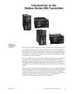
Introduction to the Watlow Series 988
Controllers
ii Using this Manual
ii Document Every Step
iii Notes, Cautions and Warnings
iii Technical Assistance
iii We Value Your Feedback
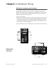
Chapter 1
Hardware Setup
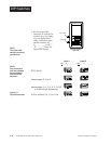
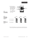
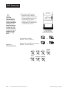
1.1 Dip Switch Locations and Functions
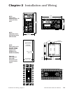
Chapter 2
Installation and Wiring
2.1 Panel Cutout and Dimensions
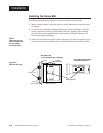
2.2 Installing the Series 988
2.4 Wiring the Series 988
2.4 Input-to-output Isolation
2.4 Power Wiring
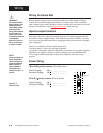
2.5 Sensor Installation Guidelines
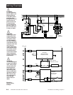
2.6 Wiring Example
2.8 Input 1 Wiring
2.9 Input 2 Wiring
2.11 Event Input 1 Wiring
2.12 Output 1 Wiring
2.13 Output 2 Wiring
2.14 Output 3 Wiring
2.15 Output 4 Wiring
Chapter 3
Front Panel and Display Loop
3.1 Keys and Displays
3.2 Display Loop
Chapter 4
The Setup Menus
4.1 Navigating the Setup Menus
4.2 Input Menu
4.18 Output Menu
4.34 Global Menu
4.44 Communications Menu
Chapter 5
The Operation Menus
5.1 Navigating the Operation Menus
5.2 System Menu
5.9 PID A and PID B Menus
Chapter 6
The Factory Menus
6.1 Navigating the Factory Menus
6.2 Panel Lockout Menu
6.7 Diagnostics Menu
6.13 Calibration Menu
Chapter 7
Tuning, Manual Operation,
Alarms and Error Codes
7.1 Auto-tuning (Heat and/or Cool)
7.2 Manual Tuning
7.4 Manual and Automatic Operation
7.5 Changing the Output 3 Alarm Jumper
7.6 Using Alarms
7.8 Error Code E1 and E2 Messages
7.9 Error Code Actions
Chapter 8
General Software
8.2 Burst Fire
8.4 Communications
8.6 Dead Band
8.8 Digital Events
8.10 Heater Current
8.12 Input Filter
8.14 Input Linearization
8.16 Ramp to Set Point
8.18 Remote Set Point
8.20 Retransmit
8.22 Slidewire Feedback
Chapter 9
Enhanced Software
9.2 Cascade
9.6 Differential
9.8 Dual PID Sets
9.10 Duplex
9.12 Ratio
Appendix
A.2 Glossary
A.4 Specifications
A.5 Warranty and Returns
A.6 Index
A.10 Menu Overview
A.11 Model Number – Ordering Information
A.12 Declaration of Conformity