


WATLOW Series 988 User’s Manual 2.15
Installation and Wiring, Chapter 2
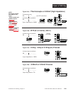
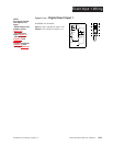
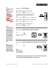
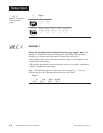
Figure 2.15b — Switched DC, Open Collector
98 _ _ - _ _ _ _ - _ C _ _
Maximum voltage: 42V
ÎÎ
(dc)
Maximum current: 1A
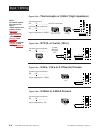
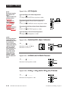
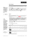
Figure 2.15a — AC Outputs
Solid-state Relay
with
Contact Suppression
98 _ _ - _ _ _ _ - _ B _ _
0.5 amps, minimum off-state impedance: 20KΩ
Electromechanical Relay
with
Contact Suppression
(Suppression between NO and COM contacts only)
98 _ _ - _ _ _ _ - _ D _ _ _
Form C, 5 amps, minimum off-state impedance: 20KΩ
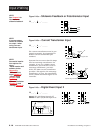
Electromechanical Relay
without
Contact Suppression
98 _ _ - _ _ _ _ - _ E _ _ _
Form C, 5 amps, off-state impedance: 31MΩ
Solid-state Relay
without
Contact Suppression
98 _ _ - _ _ _ _ - _ K _ _ _
0.5 amps, off-state impedance: 31MΩ
Output 4 Wiring
External
Load
COM
L1
L2
Fuse
NO
5
6
NC
(#7 for D & E outputs only)
7
5
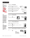
External
Load
6
+
7
-
COM
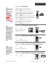
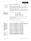
Figure 2.15c — External Signal Conditioner Power Supply
98 _ _ - _ _ _ _ - _ T _ _
5
6
+
-
+V
-V
Transmitter
4-20mA out
Input
1 or 2
+
-
For data communications wiring refer to
Data Communications
with the Watlow Series 988 Family of Controllers.
NOTE:
Input-to-output iso-
lation is defeated
when the external
transmitter power
supply is used to
power a signal con-
ditioner connected
to input 1 or input 2.
˜
NOTE:
See Chapter 1 for
power supply DIP
switch information.
NOTE:
Successful installa-
tion requires five
steps:
• Model number and
software choice
(Appendix);
• DIP switch set-
tings (Chapter 1);
• Sensor match
(Chapter 2 and
Appendix);
• Sensor installation
(Chapter 2); and
• Wiring (Chapter 2).
+
Internal Circuitry
5
6
7
790Ω
19 to 32VÎ (dc)
NOTE:
Switching inductive
loads (relay coils,
solenoids, etc.) with
the mechanical
relay or solid state
relay output options
requires using an
R.C. suppressor.
Watlow carries the
R.C. suppressor
Quencharc brand
name, which is a
trademark of ITW
Paktron. Watlow
Part No. 0804-0147-
0000.
Loop powered