


1.2 WATLOW Series 988 User’s Manual
Hardware Setup, Chapter 1
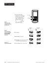
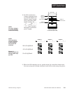
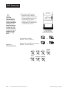
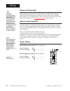
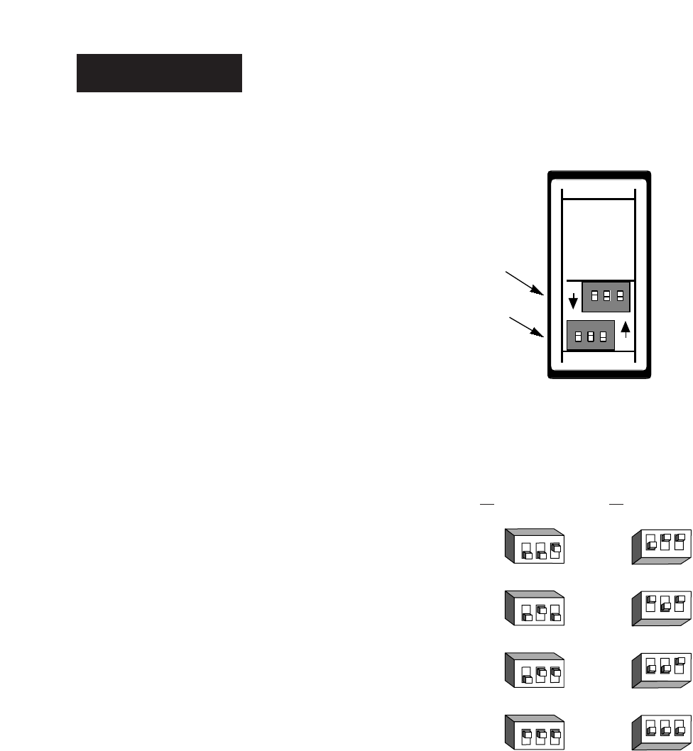
DIP Switches
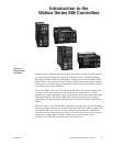
Figure 1.2 -
Input DIP switches.
Input 1 Input 2
(98 _ _-2_ _ _-_ _ _ _)(98 _ _-_2_ _-_ _ _ _)
RTD (100 Ω)
thermocouple: R, S or B
thermocouple: J, K, T, N, E, C, D, Pt2
or 0-50mV (high impedance)
0-20 or 4-20mA; 0-5, 1-5 or 0-10V
O
N
↑
123
O
N
↑
123
O
N
↑
123
O
N
↑
123
O
N
↑
123
O
N
↑
123
O
N
↑
123
O
N
↑
123
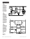
Controller Chassis
Rear View
Input 1 DIP
Input 2 DIP
ON
ON
1. Set the input DIP
switches to match the
sensors you are using
in your application.
Only controllers with
model number 98_ _-
2_ _ _-_ _ _ _ or 98_ _-
_2_ _-_ _ _ _ have an
input DIP switch.
˜
NOTE:
The Input 2 DIP
switch is mounted
upside down.
˜
NOTE:
Only controllers
with the indicated
model numbers
have these DIP
switches.