


WATLOW Series 988 User’s Manual 8.23
General Software Features, Chapter 8
TLTL
WW
WW
AA
PROCESS
L1 L2 L3 L4
DEV
% OUT
DISPLAY
MODE
AUTO
MAN
SERIES 988
input 1
input 2
slidewire input
output 1 (close)
output 2 (open)
gas
flow
gas valve
cut-off
valve
Valve Actuator
limit
Gas-fired Furnace
limit
sensor
temperature
sensor
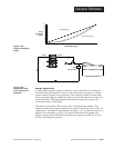
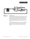
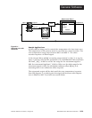
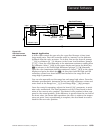
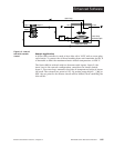
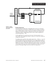
Sample Application
A Series 988 controls the gas valve for a gas-fired furnace to heat treat
large metal parts. First the controller must be “married” to the slidewire
feedback from the valve actuator. To do this, first set the Input 2 prompt
[`In2] to slidewire [Slid]. Advance to the Learn Low Resistance prompt
[LrnL]. Close the valve manually to the minimum resistance reading from
the slidewire. Select [`yes] in the upper display and press the Mode key
µ to advance to the Learn High Resistance prompt [LrnH]. Manually
open the valve (maximum slidewire resistance). Select [`YES] in the upper
display and press the Mode key µ. At this point both the high and low
resistance values have been learned and stored in the range low 2 and
range high 2 parameters.
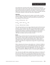
You can also manually set the range low and range high values. From the
slidewire specifications, determine the low and high resistance values and
enter these at the Range Low [`rL2] and Range High [`rH2] prompts.
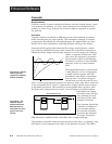
Once the control is operating, adjust the hunt [hunt] parameter, to mini-
mize valve oscillations. The hunt parameter sets up a dead band on both
sides of the current valve position. The desired valve position is then com-
pared to the actual position. If the difference is greater than the one-half of
the hunt value, the Series 988 repositions the valve to achieve the temper-
ature set point. Once repositioning is complete, the dead band is recalcu-
lated for the new valve position.
Figure 8.23 -
Gas-fired furnace
with slidewire feed-
back.
General Software