


WATLOW Series 988 User’s Manual 2.5
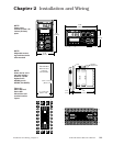
Installation and Wiring, Chapter 2
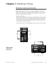
Wiring
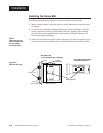
Sensor Installation Guidelines
Maintain isolation between input 1 and input 2 to prevent a ground loop.
A ground loop may cause incorrect readings, dashes across the upper dis-
play or the display of error codes.
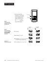
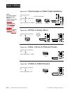
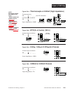
Thermocouple input: Extension wire for thermocouples must be of the
same alloy as the thermocouple itself to limit errors.
Using grounded thermocouples for both input 1 and input 2 may create
ground loop problems. To correct this problem, replace at least one of the
grounded thermocouples with an ungrounded thermocouple. If the appli-
cation requires grounded thermocouples, use an isolated transmitter,
such as a Watlow Gordon 5702 isolated transmitter.
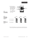
RTD (100 Ω) input: Each 1Ω of lead wire resistance can cause a +2°C
error when using a two-wire RTD. A three-wire RTD sensor overcomes this
problem. All three wires must have the same electrical resistance (i.e.,
same gauge, same length, multi-stranded or solid, same metal).
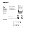
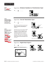
Process input: Isolation must be maintained between input 1 and input
2. If both input 1 and input 2 are used as process inputs, a separate
power supply and transmitter must be used for each input. Output option
T (external signal conditioner power supply) can be used to supply power
for only one input.
ç
CAUTION:
The Series 988 will
not function with
two grounded ther-
mocouple inputs.
Avoid using a
grounded thermo-
couple for both
input 1 and input 2.
Failure to follow this
guideline could
result in damage to
equipment.
NOTE:
Input-to-output iso-
lation is defeated
when the external
signal conditioner
power supply is
used to power a
transmitter connect-
ed to input 1 or
input 2.