


2.6 WATLOW Series 988 User’s Manual
Installation and Wiring, Chapter 2
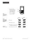
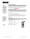
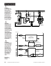
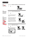
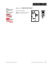
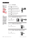
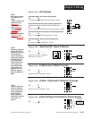
Wiring Example
Figure 2.6 -
System wiring
example.
988A-10CA-AARR
rear view
(+)
10
9
2221
12
13
(-)
L1
L2
(-)
120VÅ (ac)
fuse
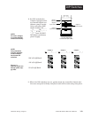
92A3-1DJ1-0000
limit control
heater
process sensor limit sensor
optional
normally open
momentary switch
red
high-limit
mechanical
contactor
earth ground
(+)
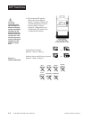
dc input
SSR
SSR-240-10A-DC1
in
out
1 2
4 3
13 14
10
+
11
-
high-temperature
light
coil
11
1 5
1
120VÅ (ac)
L1
L2
2
9
10
4
5
1 2
1
2
(+)
(-)
3
11
18
12
13
14
15
2
1CR
16
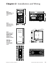
high-temperature light
1
2
3
4
8
9
10
11
12
R
SSR-240-10A-DC1
solid-state relay, dc input
17
1
8
heater
out
24-240VÅ (ac)
(+)
(-)
in
3-32VÎ (dc)
1 CR-1
9 10
2
12 13
6 7
21 22
5
6
7
limit control
Series 988
988A-10CA-AARR
temperature control
Series 92
92A3-1DJ1-0000
13
4
3
5
11
1 2
13
14
10
(+)
(-)
11
∫
WARNING:
To avoid potential
electric shock, use
National Electric
Code (NEC) safety
practices when
wiring and connect-
ing this unit to a
power source and
to electrical sen-
sors or peripheral
devices. Failure to
do so could result
in injury or death.
ç
WARNING:
Install high or low
temperature limit
control protection
in systems where
an over tempera-
ture fault condition
could present a fire
hazard or other haz-
ard. Failure to
install temperature
limit control protec-
tion where a poten-
tial hazard exists
could result in dam-
age to equipment,
property and injury
to personnel.
ç
WARNING:
To avoid damage to
property and equip-
ment, and/or injury
of loss of life, use
National Electric
Code (NEC) stan-
dard wiring prac-
tices to install and
operate the Series
988. Failure to do
so could result in
such damage,
and/or injury or
death.