


20
19
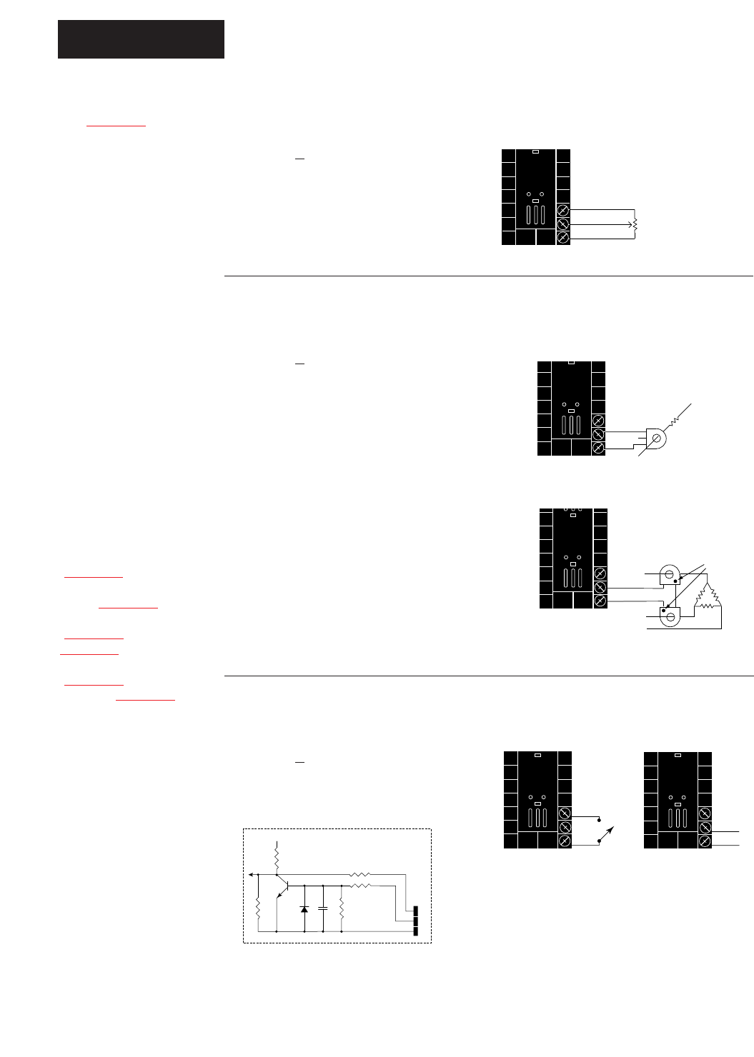
T3
T1
T2
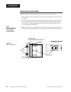
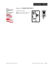
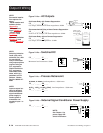
Phase
dot
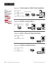
3-phase using 2 current transformers
Figure 2.10b — Current Transformer Input
98 _ _ - _ 4 _ _ - _ _ _ _
The current transformer must be pur-
chased separately. See Appendix for
Watlow current transformer part
numbers.
Systems that use more than 50 Amps
need an interstage transformer. For
example, if you use a 300A current
transformer, part #16-0073, and an
interstage transformer, part #16-
0176, the 300A current transformer
provides a 5A signal to the interstage
transformer. In turn, the transformer
sends a 20mA maximum signal to the
controller.
2.10 WATLOW Series 988 User’s Manual
Installation and Wiring, Chapter 2
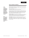
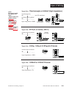
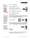
Input 2 Wiring
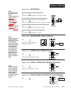
Figure 2.10c — Digital Event Input 2
98 _ _ - _ 5 _ _ - _ _ _ _
open 0-3VÎ (dc) Event Input 2 off
closed 14-36VÎ (dc) Event Input 2 on
20
19
L2
L1
CT
Load wire
Center leg not used
Single-phase
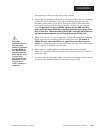
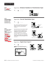
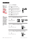
Figure 2.10a — Slidewire Feedback or Potentiometer Input
98 _ _ - _ 3 _ _ - _ _ _ _
19
20
18
CW
CCW
Wiper
NOTE:
See Chapter 8 for
information on
slidewire feedback.
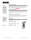
20
18
+5VÎ (VDC)
100Ω
750Ω
4.7KΩ
1KΩ
.01µf
19
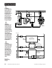
Internal Circuitry
˜
NOTE:
A process output
cannot be installed
on output 1 when
using a current
transformer input.
20
18
20
19
+
-
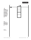
NOTE:
Successful installa-
tion requires five
steps:
• Model number and
software choice
(Appendix);
• DIP switch set-
tings (Chapter 1);
• Sensor match
(Chapter 2 and
Appendix);
• Sensor installation
(Chapter 2); and
• Wiring (Chapter 2).