


WATLOW Series 988 User’s Manual 2.1
Installation and Wiring, Chapter 2
Chapter 2 Installation and Wiring
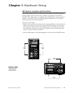
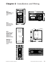
Panel Cutout
Maximum Panel
Thickness
0.38" (9.65mm)
3.62" + 0.03 -0.00
(92mm + 0.8)
1.77 + 0.02 -0.00
(45mm + 0.6)
4.03"
(102mm)
2.18"
(55 mm)
TL
W
W
A
PROCESS
L1 L2 L3 L4
DEV
% OUT
DISPLAY
SERIES 988
MODE
AUTO
MAN
4.03"
(102mm)
2.18"
(55 mm)
TL
W
W
A
PROCESS
L1 L2 L3 L4
DEV
% OUT
MODE
SERIES 989
DSPY
AUTO
MAN
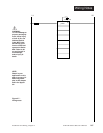
Figure 2.1 -
Series 988 and
Series 989
dimensions and
terminal number
layout.
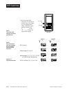
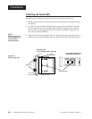
Panel
Adjustable
Mounting Bracket
4.06"
(103 mm)
0.68"
(17 mm)
˜
NOTE:
Adjustable mount-
ing brackets can be
side-mounted.
˜
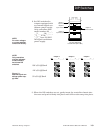
NOTE:
Space panel
cutouts at least 1.66
inches (42.2mm)
apart.
˜
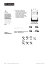
NOTE:
Holes can be cut in
the panel using a
Greenlee 1/8 DIN
Hydraulic Kit
#60068 (punch
#60069, die #60070).
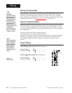
12
13
14
15
16
17
18
19
3
4
5
6
7
8
9
11
22
21
1
20
23
10
24
2
12
13 14
15 16
17
18
19
2
3
45
67
89
11
22
21
1
20
24
23
10