


9.2 WATLOW Series 988 User’s Manual
Enhanced Software Features, Chapter 9
Enhanced Software
Cascade
Requirements
Cascade control requires enhanced software and two analog inputs, input
1 to monitor the primary, or outer, loop and input 2 to monitor the sec-
ondary, or inner, loop. At least one control output is required to control
the process.
Overview
Cascade control can handle a difficult process with minimal overshoot,
while reaching the set point quickly. This minimizes damage to system
components and allows for oversizing heaters for optimal heat-up rates.
Heater life is also extended by reducing thermal cycling of the heater.
Systems with long lag times between the energy source (heater, steam,
etc.) and the measured process value cannot be controlled accurately or
efficiently with a single control loop, because a lot of energy can build up
before a response is detected. This
can cause the system to overshoot
the set point, which could damage
the heater, product or heat transfer
medium, such as a heat transfer
fluid.
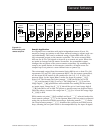
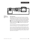
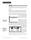
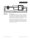
This graph illustrates a system with
a long lag time. Curve A represents
a single-control system with PID
parameters that allow a maximum
heat-up rate. Too much energy is
introduced and the set point is over-
shot. In most long-lag-time systems the process value may never settle out
to an acceptable error. Curve C represents a single-control system tuned
to minimize overshoot. This results in unacceptable heat-up rates, with
the final value taking hours to reach. Curve B shows a cascade system
that limits the energy
introduced into the sys-
tem, allowing an opti-
mal heat-up rate with
minimal overshoot.
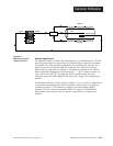
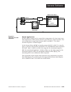
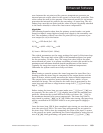
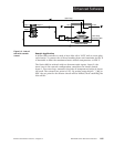
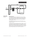
This drawing shows two
controllers configured
as a cascade system.
The second controller
generates the internal
set point. The Series
988 effectively combines both controllers into a single package.
The primary controller measures the process in the outer, or primary, loop
with input 1 and compares the value to the desired set point. The differ-
input 1
Two controllers in one
input 2
output 1
Outer-loop
Controller
Inner-loop
Controller
% int
% out
In2
In1
SP SPint
A
B
C
time
set
point
Figure 9.2b - The
cascade feature
allows one Series
988 controller to
internalize the func-
tions of two con-
trollers.
Figure 9.2a - System
heat-up profiles
using three different
control methods.