


WATLOW Series 988 User’s Manual 1.1
Hardware Setup, Chapter 1
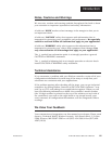
Chapter 1 Hardware Setup
DIP Switch Locations and Functions
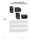
The Watlow Series 988 has at least one and as many as six dual in-line
package (DIP) switches inside the controller, depending on the model
number. They allow users to configure the controller for a variety of input
sensors, to provide power for external signal conditioners or to lockout
front panel access to some functions.
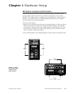
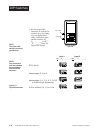
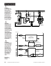
To set any DIP switch:
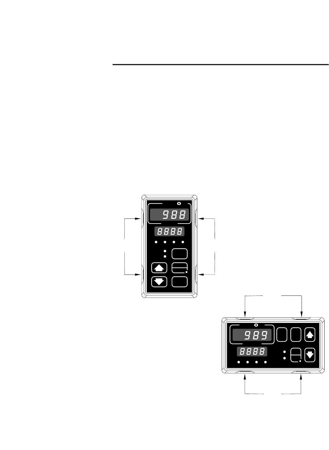
• Remove the controller from the case by pressing firmly on the two release
tabs on one side or the top of the bezel until they unsnap. Then firmly
press the two release tabs on the opposite side or the bottom of the con-
trol until they unsnap. You will need to gently rock the bezel back and
forth to release it from the chassis.
• Use the illustrations on the following pages to locate and set each DIP switch.
TL
W
W
A
PROCESS
L1 L2 L3 L4
DEV
% OUT
DISPLAY
SERIES 988
MODE
AUTO
MAN
Release
Tabs
Release
Tabs
TL
W
W
A
PROCESS
L1 L2 L3 L4
DEV
% OUT
MODE
SERIES 989
DSPY
AUTO
MAN
Release
Tabs
Release
Tabs
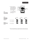
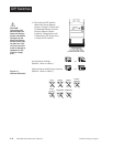
Figure 1.1 - Press
the release tabs to
remove the con-
troller chassis.