


WATLOW Series 988 User’s Manual 2.11
Installation and Wiring, Chapter 2
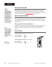
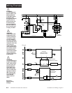
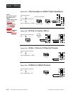
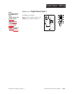
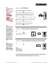
Figure 2.11a — Digital Event Input 1
Available on all units.
open 14-36VÎ (dc) Event Input 1 off
closed 0-3VÎ (dc) Event Input 1 on
23 24
+ -
24
23
+24VÎ (dc)
10KΩ
4.99KΩ
OPTO
ISOLATOR
750Ω
.01µf
4.99KΩ
Internal Circuitry
NOTE:
Successful installa-
tion requires five
steps:
• Model number and
software choice
(Appendix);
• DIP switch set-
tings (Chapter 1);
• Sensor match
(Chapter 2 and
Appendix);
• Sensor installation
(Chapter 2); and
• Wiring (Chapter 2).
Event Input 1 Wiring