


ii WATLOW Series 988 User’s Manual
Introduction
Introduction
Using this Manual
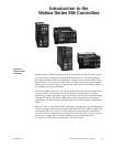
This manual provides the information you will need to install and operate
a Series 988 controller.
If you need information about Series 988 configurations and model num-
bers, refer to the Appendix of this manual or, for more detailed informa-
tion, to Optimizing Your Process System with the Series 988 Controller: An
Application Guide for the Watlow Series 988 Family.
If your Series 988 controller will be used for data communications, you
will also need our communications manual, Data Communications with the
Watlow Series 988 Family of Controllers (green cover).
Series 988 controllers are calibrated in the factory, but if you need to do
periodic calibration you will need our calibration manual, Calibrating
Watlow Process Controllers, (blue cover).
This manual explains the five steps of setting up a Series 988 controller:
1. Set and document all of the DIP switches, if applicable: Chapter 1.
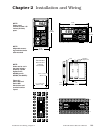
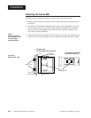
2. Mount the controller: Chapter 2.
3. Wire and document the controller wiring: Chapter 2.
4. Configure and document the controller software: Chapters 3-6.
5. Run, test and adjust your application. Update documentation.
Chapters 7 and 8 and the Appendix provide detailed advice, definitions
and specifications along with application examples to help you optimize
the safety and performance of your application. Use the Table of Contents
and Index to find specific information.
Document Every Step
The Series 988 provides powerful and complex features. Carefully docu-
ment each step of the setup and any subsequent changes. This will make
it much easier to change, adjust and troubleshoot your application.
Make the configuration documentation available to engineers and techni-
cians, on all shifts, who may need to work with the Series 988. We provide
space in this manual to record configurations. You may prefer to photo-
copy the blank forms and keep them in a separate binder. However you
maintain your documentation, be sure to replace all old copies of the doc-
umentation with updated versions whenever the controller configuration is
changed.
˜
NOTE:
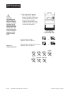
The Menu Overview
in the Appendix
shows all the
menus and
prompts.
˜
NOTE:
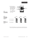
The 12-digit number
is printed on the top
of the stickers on
each side of the
controller’s case
and on the right-
hand or top circuit
board.