


SP2
IdSP
Set point 2
Idle set point
( )
( )
Operation
OPEr
( )
Setup
SEt
( )
Fcty
Factory
( )
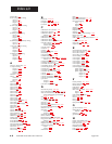
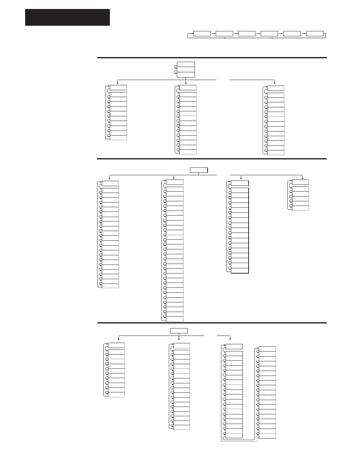
A.10 WATLOW Series 988 User’s Manual
Appendix
(SyS)
Alarm 2 low
Event input 2 status
Alarm 2 high
Alarm 3 low
Alarm 3 high
(System)
Event input 1 status
Ei1S
A2LO
A2HI
A3LO
A3HI
Ei2S
A4LO
AUt
L-r
A4HI
( )
( )
( )
( )
( )
( )
( )
( )
( )
( )
Auto-tune
Alarm 4 high
Local-remote
Alarm 4 low
(PIDA)
Output 1 integral A
Output 1 reset A
Output 1 rate A
Output 1 derivative A
Output 1 cycle time A
(PIDA)
Output 1 proportional band A
Pb1A
It1A
rA1A
dE1A
Ct1A
rE1A
Pb2A
It2A
rA2A
rE2A
( )
( )
( )
( )
( )
( )
( )
( )
( )
( )
Output 2 integral A
Output 2 reset A
Output 2 rate A
Output 2 proportional band A
Ct2A
db A
dE2A
( )
( )
( )
Output 2 cycle time A
Output 2 derivative A
Dead band A
(PIDB)
Output 1 integral B
Output 1 reset B
Output 1 rate B
Output 1 derivative B
Output 1 cycle time B
(PIDB)
Output 1 proportional band B
Pb1b
It1b
rA1b
dE1b
Ct1b
rE1b
Pb2b
It2b
rA2b
rE2b
( )
( )
( )
( )
( )
( )
( )
( )
( )
( )
Output 2 integral B
Output 2 reset B
Output 2 rate B
Output 2 proportional band B
Ct2b
db b
dE2b
( )
( )
( )
Output 2 cycle time B
Output 2 derivative B
Dead band B
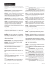
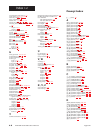
At the [`SEt] prompt, press > and < another
3 seconds to enter the Factory menus.
Press > and < for 3 seconds to enter
the Setup menus. Outputs are disabled.
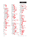
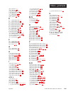
Figure A.10 -
The Series 988 Map.
75 50 °F0
% OUT LED onDEV LED on Process unitsProcess input 2
Pr 2
Set point 1,
Remote
set point or
Ratio value
Inner Loop
set point
(cascade only)
InSP
(InPt)
Range high 1
Range low 1
Calibration offset 1
Decimal place 1
(Input)
Input 1
In1
rH1
CAL1
dEC1
rL1
Lin1
rSP
rL2
rH2
CAL2
In2
rtd2
Ftr2
Lin2
Hunt
( )
( )
( )
( )
( )
( )
( )
( )
( )
( )
( )
( )
( )
( )
( )
( )
Remote set point
Input 2
Range low 2
Range high 2
Calibration offset 2
Input 1 linearization
RTD calibration curve 2
Input 2 software filter
Input 2 linearization
Slidewire dead band
dEC2
Decimal place 2
Input 1 software filter
Ftr1
RTD calibration curve 1
rtd1
( )
( )
( )
( )
LrnL
LrnH
Learn range low
Learn range high
SHyS ( )
Slidewire inner
hysteresis
Retransmit low limit
Retransmit high limit
Retransmit cal. offset
(OtPt)
Hysteresis 1
Process 1
Output 2
Process 2
Hysteresis 2
(Output)
Output 1
Ot1
HYS1
Ot2
Prc2
HYS2
Prc1
SP2c
LAt2
SIL2
A3Sd
HYS3
AL2
LAt3
SIL3
A4Sd
HYS4
( )
( )
( )
( )
( )
( )
( )
( )
( )
( )
( )
( )
( )
( )
( )
( )
Latching for alarm 2
Alarm 2
Silence alarm 2
Alarm 3 side
Hysteresis 3
Control set point 2
Latching for alarm 3
Silence alarm 3
Alarm 4 side
Hysteresis 4
LAt4
SIL4
Aout
A r L
A r H
( )
( )
( )
( )
( )
Latching for alarm 4
Silence alarm 4
Analog output
ACAL
Ot3
Ot4
( )
( )
( )
Output 3
Output 4
( )
Prc3
Process 3
AL4
( )
Alarm 4
AL3
Alarm 3
( )
A2Sd
( )
Alarm 2 side
(COM)
Protocol type
Data bits and parity
Address
Interface type
(Communications)
Baud rate
bAUd
Prot
Addr
intF
dAtA
( )
( )
( )
( )
( )
(gLbL)
Failure mode
Error latching
Control type
(Global)
Celcius_Fahrenheit
C_F
FAIL
Err
CntL
CSAC
Proc
StPt
Ei1
Pid2
Ei2
Anun
HiP
AtSP
( )
( )
( )
( )
( )
( )
( )
( )
( )
( )
( )
( )
( )
Crossover process value
PID 2 crossover selectio
n
Crossover set point valu
e
Event input 1
Cascade action
Event input 2
Annunciator
High power limit
Auto-tune set point
rP
rAtE
( )
Ramping function
Ramp rate
LoP
( )
( )
Low power limit
ALgO ( )
Control algorithm
(PLOC)
PIDA menu lockout
System menu lockout
PIDB menu lockout
Input menu lockout
Output menu lockout
(Panel Lockout)
Front Panel lockout
Diagnostics menu lockout
Communications menu lockout
Global menu lockout
Calibration menu lockout
LOC
PidA
Pidb
InPt
OtPt
SyS
gLbL
COM
diAg
( )
( )
( )
( )
( )
( )
( )
( )
( )
CAL
( )
Test output
(diAg)
Software revision
Serial number
Ambient temperature
Ambient A/D count
(Diagnostics)
Factory ship date
dAtE
SOFt
Sn
AMb
Acnt
gnd
cnt2
ity1
ity2
cnt1
Oty1
Oty2
Oty4
dISP
( )
( )
( )
( )
( )
( )
( )
( )
( )
( )
( )
( )
( )
Input 2 A/D count
Input 1 A/D count
Input 1 module
Input 2 module
Ground A/D count
Output 1 module
Output 2 module
Output 4 module
Test displays
tout
( )
Oty3
( )
( )
Output 3 module
Open loop
OPLP
( )
(CAL)
(Calibration)
A 50
tc
A 0H
A 20
A 15
A 00
A380
A 0u
A20A
b 15
b380
A10U
b10U
b 0U
b 4A
b 0u
( )
( )
( )
( )
( )
( )
( )
( )
( )
( )
( )
b100
1 4
1 20
1 0
1 10
2 4
A 4A
b20A
Default prompts
2 20
2 0
2 10
3 LO
3 HI
rSt
dFL
A 0u
A100
b 00
b 0H
b 50
( )
( )
( )
( )
( )
( )b 20
Restore factory values
( )
( )
( )
( )
( )
( )
( )
( )
( )
( )
( )
( )
( )
( )
( )
( )
( )
( )
( )
( )
˜
NOTE:
This is a complete
listing of all Series
988 prompts.
Not all prompts will
appear on your con-
trol. They are
dependent on your
configuration and
model number.
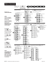
Operation Menus
Display Loop
(Lower Display)
Setup Menus
Factory Menus
To navigate:
Press ¥ to return
to the Display Loop
from any location and
to advance through
the Display Loop.
Press > or < to
move between the
menus.
Press µ to
advance through a
menu.
Hold µ while
pressing > to
move backwards
through the menus.
Press > or < to
select prompt values.
Press µ to advance to the Operation
menus. Outputs are still active.
Press ¥ to exit
any menu and
reach the Display
Loop at any time.
Menu Overview
µ
µ
µ
µ
µ
µ
µ
µ
µ
µ
>
>
>
NOTE:
The controller will
not default back to
normal display
while in the Factory
Menu. All outputs
are disabled while
in this menu.