


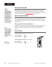
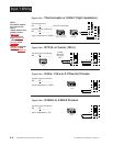
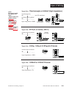
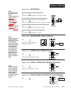
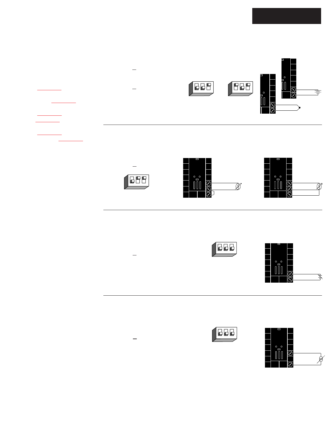
Figure 2.9d — 0-20mA or 4-20mA Process
Universal signal conditioner
98 _ _ - _ 2 _ _ - _ _ _ _
Input impedance: 7Ω
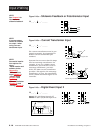
Figure 2.9c — 0-5V
ÎÎ
, 1-5V
ÎÎ
or 0-10V
ÎÎ
(dc) Process
Universal signal conditioner
98 _ _ - _ 2 _ _ - _ _ _ _
Input impedance: 10KΩ
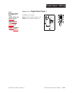
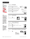
Figure 2.9b — RTD (2- or 3-wire) (100 Ω)
Universal signal conditioner
98 _ _ - _ 2 _ _ - _ _ _ _
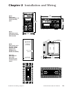
WATLOW Series 988 User’s Manual 2.9
Installation and Wiring, Chapter 2
Input 2 Wiring
20
19
-
+
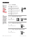
Figure 2.9a — Thermocouple or 0-50mV (high impedance)
Thermocouple only
98 _ _ - _ 1 _ _ - _ _ _ _ (no DIP switches)
Universal signal conditioner
98 _ _ - _ 2 _ _ - _ _ _ _
Input impedance: 20MΩ
19
20
+
-
Jumper
#19 to #20
for 2-wire
RTD
19
20
18
S2
S1
DIP Switch
Setting
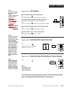
R, S, B
DIP Settings
J, K, T, N, C, E, D, Pt2,
0-50mV DIP Settings
DIP Switch
Setting
19
20
18
S2
S1
S3
O
N
↑
1 2 3
O
N
↑
1 2 3
O
N
↑
1 2 3
O
N
↑
1 2 3
20
18
-
+
DIP Switch
Setting
O
N
↑
1 2 3
19
20
+
-
0-50mV
NOTE:
Successful installa-
tion requires five
steps:
• Model number and
software choice
(Appendix);
• DIP switch set-
tings (Chapter 1);
• Sensor match
(Chapter 2 and
Appendix);
• Sensor installation
(Chapter 2); and
• Wiring (Chapter 2).