


WATLOW Series 988 User’s Manual 8.19
General Software Features, Chapter 8
General Software
Sample Application
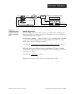
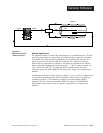
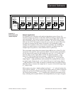
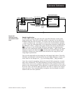
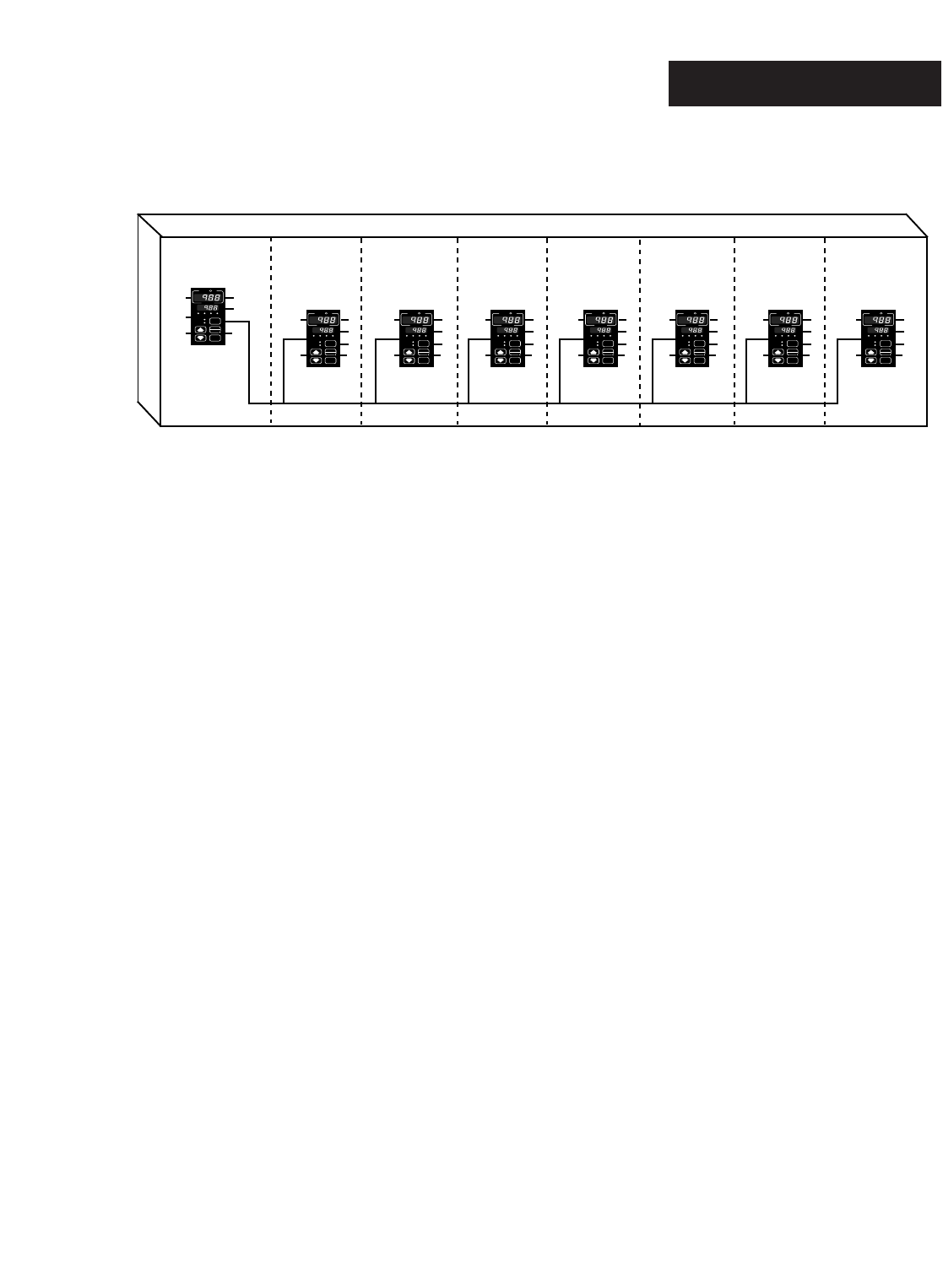
An engineer has a machine with eight independent zones of heat. He
wants to change set points on all zones without having to adjust each con-
trol individually. This can be achieved using a Series 988 with a 0-5VÎ
(dc) retransmit output as the master controller. The seven remote 988s
will use the 0-5VÎ (dc) signal on input 2 as a remote set point. When the
set point is changed on the master controller, the retransmit output
changes the set points of the seven remote controllers. By enabling the
ramp to set point feature in the master controller, all eight zones are
ramped up to set point at a user-defined rate on power up.
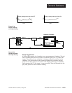
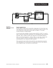
The retransmit output from the master Series 988 is set so that 0VÎ (dc)
represents 0°F and 5VÎ (dc) represents 800°F. On the remote controllers,
set the input 2 DIP switch to the position for the 0-5, 1-5, 0-10VÎ (dc)
process input. In the Input Menu, under the Input 2 prompt [`In2],
select 0-5. The Remote Set Point prompt [`rsp] should be set to ON
[``on] and decimal 2 [deC2] set to 0. The range low 2 [`rL2] and the
range high 2 [`rH2] parameters will establish the scaling for the remote
set point input. Range low 2 [`rL2] should be set to 0 and range high 2
[`rH2] should be set to 800. To operate a specific zone ten degrees hotter
than the others, increase the range low 2 [`rL2] to 10 and the range high
2 [`rH2] to 810.
With remote set point [`rSP] enabled and local [```L] selected under the
Local-remote prompt [`L-r] in the System Menu, the set point is adjusted
using the up-arrow and down-arrow keys. Selecting remote [```r] under
the Local-remote prompt [`L-r], disables the up-arrow and down-arrow
keys, allowing the set point value to be manipulated by the input 2 signal.
TLTL
WW
WW
AA
PROCESS
L1 L2L3 L4
DEV
% OUT
DISPLAY
MODE
AUTO
MAN
SERIES 988
TLTL
WW
WW
AA
PROCESS
L1 L2L3 L4
DEV
% OUT
DISPLAY
MODE
AUTO
MAN
SERIES 988
TLTL
WW
WW
AA
PROCESS
L1 L2L3 L4
DEV
% OUT
DISPLAY
MODE
AUTO
MAN
SERIES 988
TLTL
WW
WW
AA
PROCESS
L1 L2L3 L4
DEV
% OUT
DISPLAY
MODE
AUTO
MAN
SERIES 988
TLTL
WW
WW
AA
PROCESS
L1 L2L3 L4
DEV
% OUT
DISPLAY
MODE
AUTO
MAN
SERIES 988
TLTL
WW
WW
AA
PROCESS
L1 L2L3 L4
DEV
% OUT
DISPLAY
MODE
AUTO
MAN
SERIES 988
TLTL
WW
WW
AA
PROCESS
L1 L2L3 L4
DEV
% OUT
DISPLAY
MODE
AUTO
MAN
SERIES 988
TLTL
WW
WW
AA
PROCESS
L1 L2L3 L4
DEV
% OUT
DISPLAY
MODE
AUTO
MAN
SERIES 988
zone 1
Master
output 3
zone 2
Remote
input 2
zone 3
Remote
input 2
zone 4
Remote
input 2
zone 5
Remote
input 2
zone 6
Remote
input 2
zone 7
Remote
input 2
zone 8
Remote
input 2
Figure 8.19 -
Zone heating with
remote set point.