


WATLOW Series 988 User’s Manual 9.3
Enhanced Software Features, Chapter 9
Enhanced Software
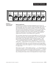
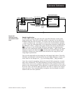
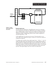
ence between the set point and the process temperature generates an
internal percent output value for the second, or inner loop, controller. This
value cannot be seen by the operator. This internal percent (% int) output
generates the internal set point for the secondary, or inner loop. The sec-
ondary loop uses this set point and the value of input 2 (typically attached
to the heater sheath) to control the heat source temperature.
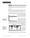
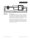
Algorithm
The following formulas show how the primary control sends a set point
(based on input 2 range-high and range-low values) to the secondary con-
trol. The secondary control uses this set point (SP int) to generate a per-
cent output (% out) to the heater.
1.) %
int
= PID Set A [In1 - SP]
2.) SP
int
= (rH2 - rL2) * %
int
+ rL2
3.) %
out
= PID Set B [In2 - SP
int
]
The critical parameters are the range settings for input 2 of the inner loop
controller. The range-high value (rH2) is the maximum allowed set point
for the secondary, or inner, loop. The range-low value (rL2) is the mini-
mum allowed set point. In a system controlling a heater this would be the
maximum and minimum desired sheath temperatures of the heater.
Typically the range-low term is set below the ambient temperature.
Otherwise the system could never fully cool down.
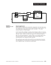
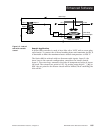
Setup
When tuning a cascade system, the inner loop must be tuned first. In a
heating system the inner loop is comprised of the output device and the
input 2 sensor, which usually measures the heater sheath temperature.
The output device controls a power switching device, which, in turn
switches the heater. The set point for the inner loop is generated by the
outer loop and will have a range between range low 2 [`rL2] and range
high 2 [`rH2].
Before tuning the inner loop you must make sure [`rL2] and [`rH2] are
set properly. Set the value of [`rL2] slightly lower than the ambient tem-
perature, otherwise the system will never fully cool down. Set [`rH2] to
the maximum desired heat source temperature. The inner loop can be
auto-tuned by setting [`AUt] to [Pidb]. While auto-tuning, the inner loop
will be controlled in an ON/OFF mode at a set point equal to [AtSP] x
[`rH2].
Once the inner loop, PID B, has completed auto-tuning, we can then auto-
tune the outer loop, PID A. The outer loop will generate the set point for
the inner loop. This is done by comparing the value of the input 1 sensor
to the process set point, performing the control algorithm by using the val-
ues of [PidA], then generating a set point between [`rL2] and [`rH2].