


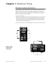

DIP Switches
WATLOW Series 988 User’s Manual 1.3
Hardware Setup, Chapter 1
Output 2
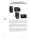
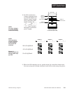
Option Board and DIP
Output 4
Option Board and DIP
Controller Chassis
Top View (986 & 988)
Left-side View (987 & 989)
Output 3
Option Board and DIP
Output 1
Option Board
offon
on
on
off
off
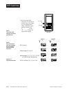
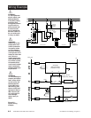
Figure 1.3 -
External signal con-
ditioner power sup-
ply DIPs.
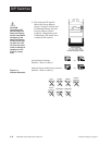
Output 2 Output 3 Output 4
(98 _ _-_ _ _T-_ _ _ _) (98 _ _-_ _ _ _-T_ _ _) (98 _ _-_ _ _ _-_T_ _)
20V ± 5% @ 30mA
12V ± 5% @ 30mA
5V ± 5% @ 30mA
O
N
↑
12
O
N
↑
12
O
N
↑
12
O
N
↑
12
O
N
↑
12
O
N
↑
12
O
N
↑
12
O
N
↑
12
O
N
↑
12
2. Set DIP switches for
outputs equipped with
an external signal con-
ditioner power supply.
Only controllers with
model number 98_ _-_
_ _T-_ _ _ _, 98_ _-_ _ _
_-T_ _ _ or 98_ _-_ _ _
_-_T_ _ have an exter-
nal signal conditioner
power supply.
˜
NOTE:
For other voltages
or current settings
contact the factory.
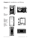
3. When the DIP switches are set, gently insert the controller chassis into
the case and push it firmly into place until all four tabs snap into place.
˜
NOTE:
Only controllers
with the indicated
model numbers
have these DIP
switches.