


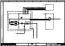

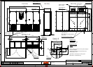

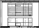

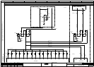

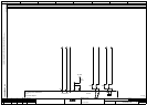

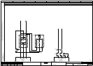

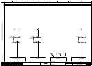

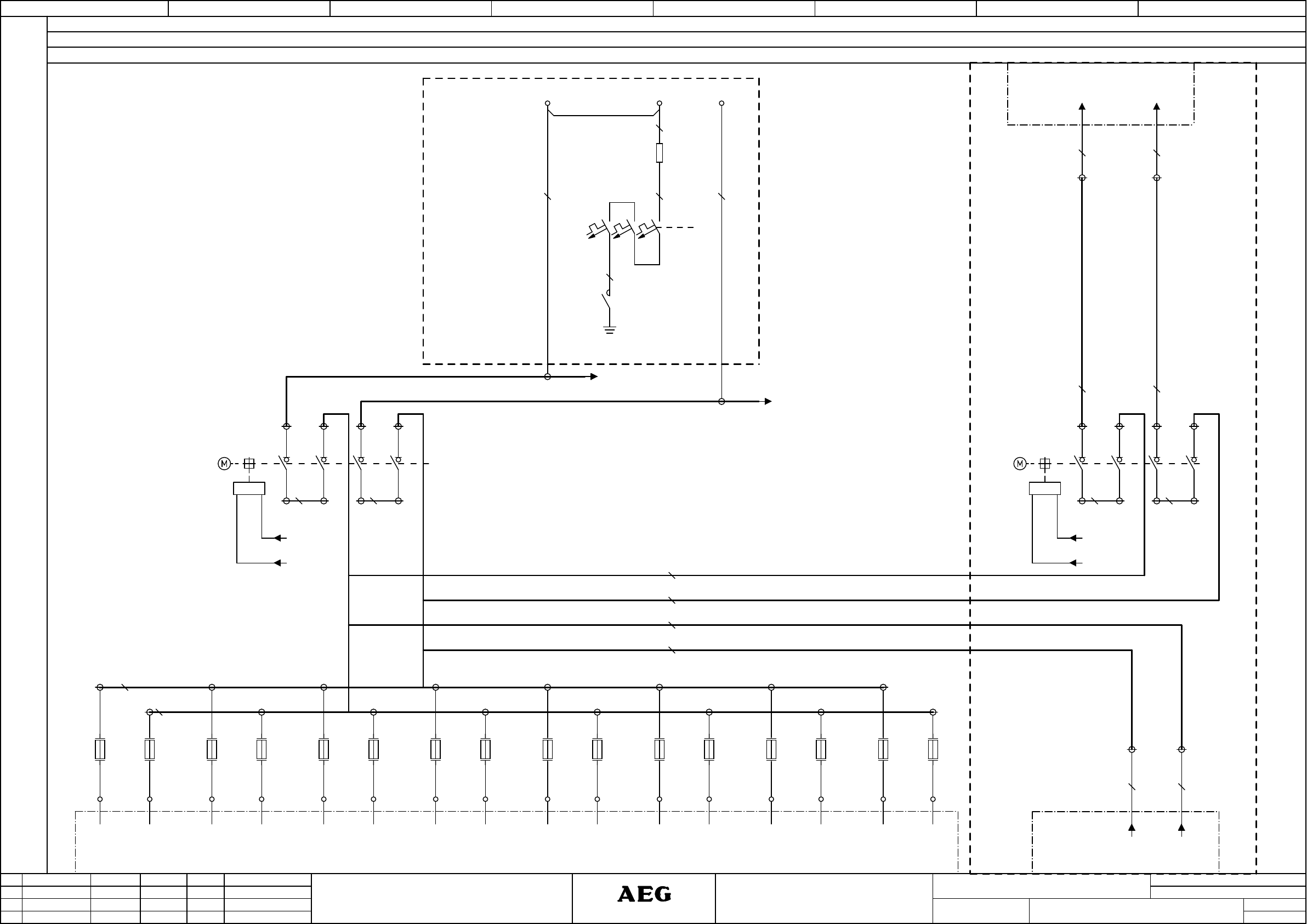
Connection diagram
1 876543
Name
=
2
15.01.2013
Checked
Alteration
2
ASPDate
Date
+Oeselke
Norm
Editor
sheets
sheet
Stat
Basisplan
1000003063 ASP
Protect PV.630
This document is property of AEG Power Solutions and must not be
displayed or duplicated to any third party without the concent of the company
CAE EPLAN Electric P8
1000003063_en
en
3
Gleitsmann
Next page
6
POWER SOLUTIONS
POWER SOLUTIONS
POWER SOLUTIONS
POWER SOLUTIONS
1L+
1L-
DC Input
active grounding
Protect PV.630
Input
Power lines
Power lines
(Custom.)
(Custom.)
(Custom.)
(Custom.)
1
2
-F41.3
1
2
-F41.4
1
2
-F41.5
1
2
-F41.6
1
2
-F41.1
1
2
-F41.2
-X41
1L+ 1L- 2L+ 2L- 3L+ 3L-
1
2
-F41.7
1
2
-F41.8
1
2
-F41.9
1
2
-F41.10
4L+ 4L- 5L+ 5L-
1
2
-F41.11
1
2
-F41.12
8L+ 8L-
System 2
Slave
1
2
-Q6
(Custom.)
3
4
5
6
7
8
D1 D2
U<
System 1
Master
D1 D2
U<
7
8
5
6
3
4
1
2
-Q4
1
2
-F41.13
1
2
-F41.14
6L+ 6L- 7L+ 7L-
1
2
-F41.15
1
2
-F41.16
4x95²
BK
4x95²
BK
L+
L-
CU1250 mm²
CU1250 mm²
X6
3 4
X6
1 2
CU60x10 mm
CU60x10 mm
CU60x10 mm
CU60x10 mm
CU60x10 mm
4x95
BK
mm²
4x95
BK
mm²
CU60x10 mm
CU60x10 mm CU60x10 mm CU60x10 mmCU60x10 mm
+1L1
-2T1
-K21
EL-
-X21
L+
1
2
-R21
1
2
3
4
5
6
-F21
10A
BK
2.5 mm²
BK
2.5 mm²
BK
2.5 mm²
BK
2.5 mm²
BK
2.5 mm²
01L+
/
01L-
/
6L+6L-
6L+ 6L-
02L+
/
02L-
/