


Protect PV.630 Operating Instructions
24 of 72 8000047961 BAL
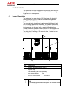
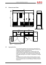
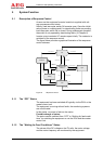
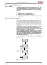
The main assemblies of the inverter are:
DC load interrupter switch Q4
Inverter stack, display and control unit with communication
components
AC filter
Inverter output contactor K7
Mains transformer (external)
Mains disconnector Q26 (external)
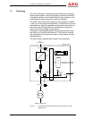
The PV cells supply the inverter stack with DC voltage via DC load
interrupter switch Q4. The inverter stack converts this DC voltage
into a 3-phase AC voltage. A sinusoidal current is fed into the
mains via the AC filter, inverter output contactor K7 and the mains
transformer.
Risk to life due to electric shock.
Potentially fatal voltages are present at the terminals on
the equipment.
Do not touch live parts.
Mains disconnector Q26 (external) and the isolator in the genera-
tor connection box (GCB) are there to isolate the inverter in the
event of unit faults or when maintenance needs to be performed
on the unit.
The control unit is supplied with power from the AC mains or, op-
tionally, from a second AC mains.
3.8 Operating Elements
For details of how the internal operating elements are arranged,
please refer to the documents included in the unit.
DANGER