


Protect PV.630 Installation and Start-up
80000047963 BAL 13 of 21
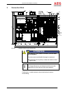
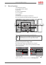
5 Connection Work
R17.4
F86
A
38.1
A
38.2
A
51
K62
F101
F84
F61
F60
F22
F13
S100
M2
X3.U
X3.V
X3.W
F86.1
2700
2
0
2
8
1800 228
1500 1200
L5.1-L5.3A86.3L4.1-L4.3 A86.2
A17
A91.1
K91
A
29.1 A27
A
115.1
A
115.2
A12 A13
A20
R17.3
C12
C13
A1
F93 F94 A31 F91 X11-X33 F83
F17 F31
F38 F51
F81
F41.1 - F41.8
X100-X500
X101,X103
X121,X201
X202,X286
X300,X500
S200
M
3
M1
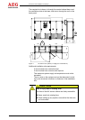
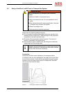
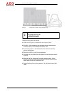
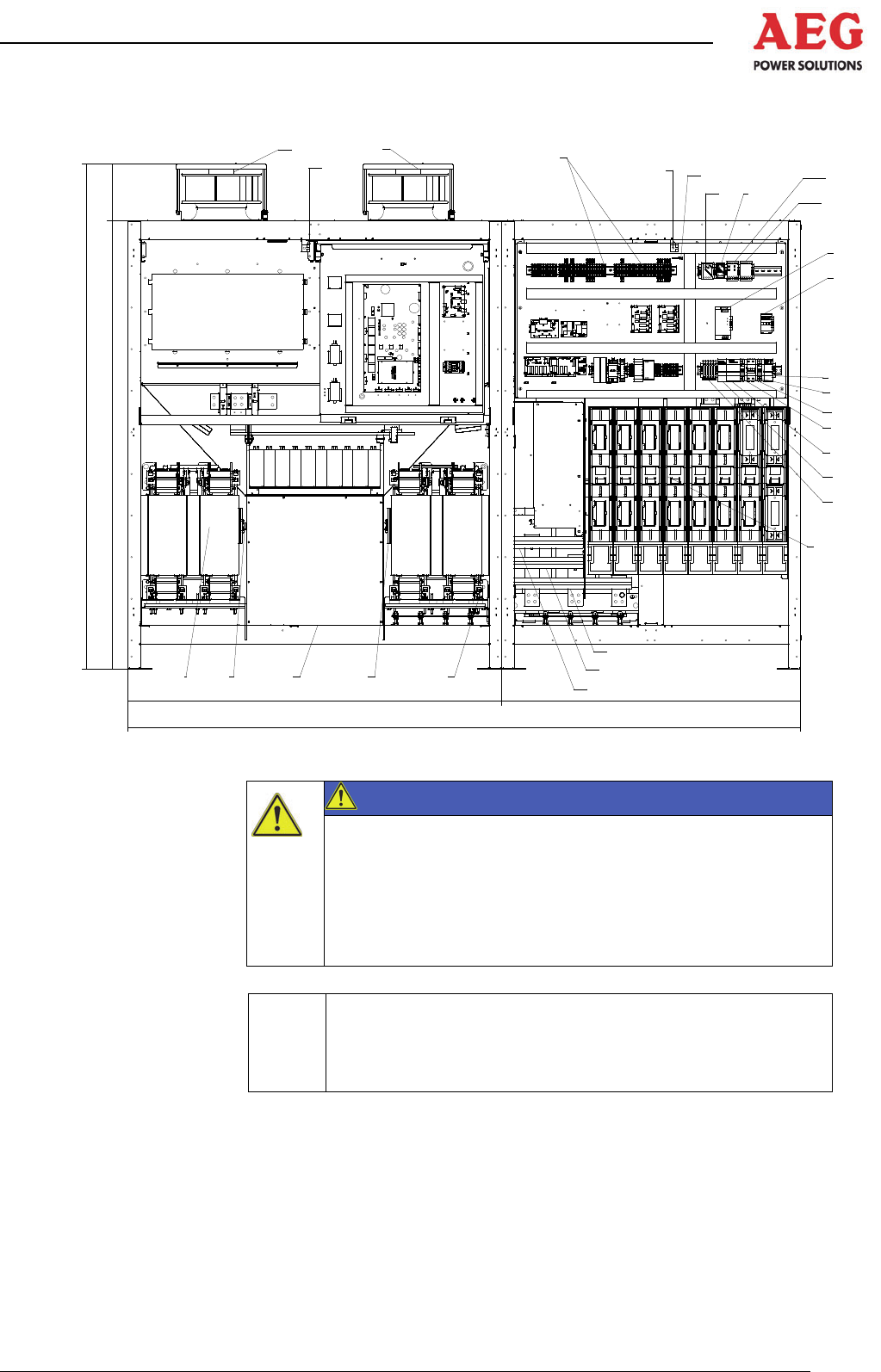
Figure 6 Installation without control cabinet doors
If the polarity of the lines is incorrect, this can dam-
age the system!
This can cause considerable damage to equipment.
Ensure the correct polarity is observed when connect-
ing the lines.
i
The image above may not always be strictly accurate,
depending on which options have been selected.
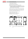
A distinction is made between internal and external connec-
tions/cabling.
ATTENTION