


Protect PV.630 Operating Instructions
8000047961 BAL 59 of 72
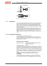
7.3 Remote Signalling
The remote signalling board is a contact interface for signalling PV
messages and controlling PV units. It is supplied as an option for
the AEG PV system and is intended for installation in the PV unit.
The remote signalling master board consists of 5 potential-free
signalling contacts and one control input.
There is an independent 24 VDC power supply for the control in-
put. The control signal is activated by bridging the relevant input.
There is no need for an additional auxiliary power supply.
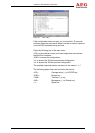
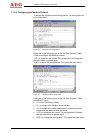
The signals are assigned as standard or can be configured on a
customer-specific basis. An integrated service switch enables
maintenance work on the unit to be signalled.
Technical data:
The maximum load for the signalling contacts (X3/X4) is 500 V/8 A
AC or 50 V/2 A DC.
I
If the specified power has been applied to the relay con-
tacts once, those contacts can no longer reliably switch
an extra-low voltage (evaporation of the gold alloy)!
The control input (X5) has an independent 24 VDC power supply.
The input is activated via a bridge.
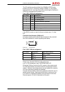
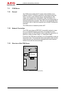
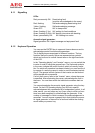
Structure:
K21
K22
K23
K24
K25
OPT1
1
1
1
1
X2
1
1
1
1
1
X3
X4
X5
X1
X6
X7
X2
S1
12
11
10
9
8
7
6
5
4
3
2
1
3
2
1
2
1
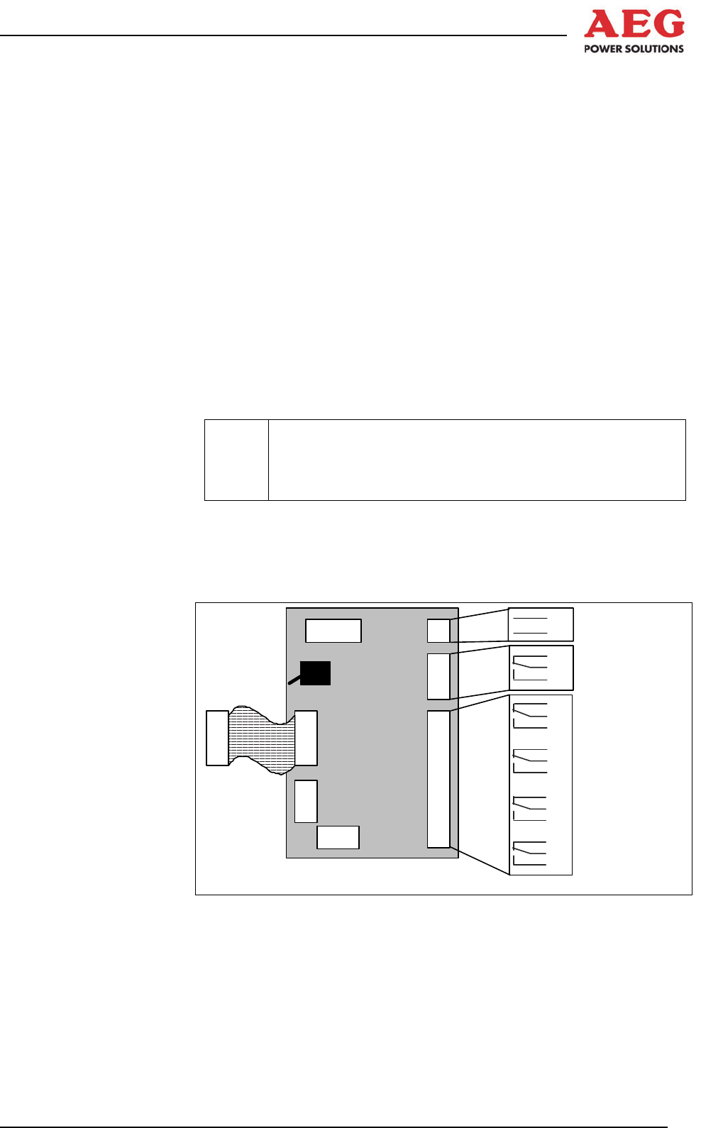
Figure 23 Remote signalling master module A12 (top view)
X1: Power supply connection
X2: Connection for remote signalling expansion boards
X3/X4: Remote signalling outputs with relay changeover
switches
X5: Remote signalling input via optocoupler with independ-
ent power supply
X6: Service plug