


Protect PV.630 Operating Instructions
8000047961 BAL 57 of 72
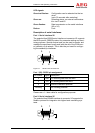
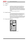
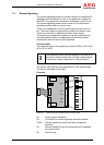
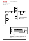
Connections:
CN1: Internal inverter bus and power supply
MOD1: Ethernet connection
CN5: Interface for firmware update
Configuration jumpers:
CN3: All closed (default)
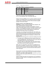
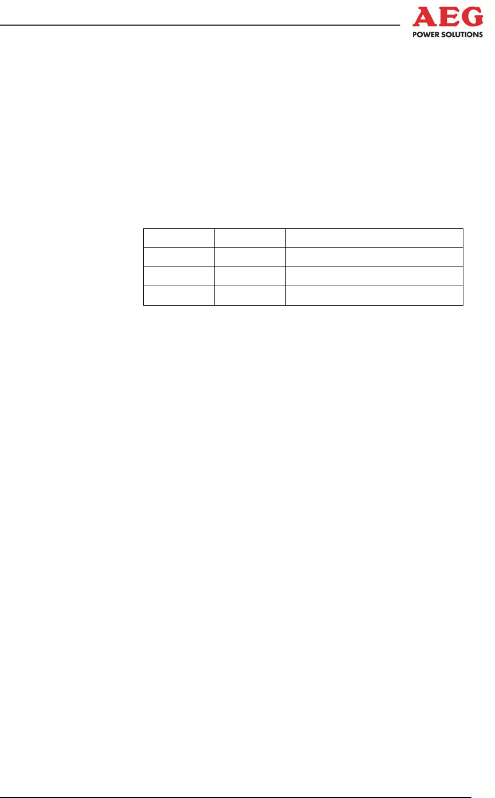
LED signals:
Green LED (H1):
The green LED on the assembly indicates the global status of the
assembly. The following signals are possible:
LED Jumper Meaning
Flashing CN3 Start-up/error
On CN3 Ready
Flickering CN3 Ethernet CAN communication
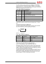
Green network LED (MOD1):
The green LED indicates communication on the network.
Yellow network LED (MOD1):
The yellow LED remains on permanently if an Ethernet network is
connected.
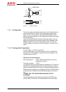
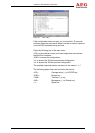
7.2.4 Installation of the COM Server
The COM server uses a communication module from Digi (“Digi
Connect ME”). In order to communicate via the COM server, it
must be integrated into the network and a virtual COM port must
be set up on a computer. The “Digi Device Discovery” tool and a
Digi RealPort driver are required for this purpose. You can find
these tools at www.digi.com/support or at www.aegps.com.
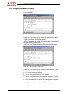
Network factory settings for the COM server:
IP address: 10.10.10.0
Subnet mask: 255.255.0.0
Default gateway: 0.0.0.0