


Protect PV.630 Installation and Start-up
14 of 21 80000047963 BAL
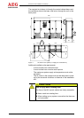
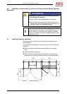
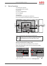
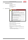
5.1 External Connections
i
Establish the connections in accordance with the circuit
diagram provided. The mains connection line for the inde-
pendent power supply must be protected by the circuit
breaker specified in the technical data sheet. See the cir-
cuit diagram and the technical data sheet for possible
connection cross-sections.
System not installed correctly!
Risk to life due to electric shock.
Only trained and qualified skilled personnel who are
authorised to install medium-voltage systems may con-
nect such equipment.
Wear personal protective equipment.
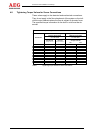
Power terminals
-X41:1L+, 1L-
to
-X41:8L+, 8L-
DC connection Maximum 185 mm²
-X3:U, V, W Mains connection Maximum 3x150 mm²/phase
PE Earth connection Maximum 2x120 mm²
X6:1, 2 Partner master Maximum 4x95 mm²/pole
X6:3, 4 Partner slave Maximum 4x95 mm²/pole
Control/Monitoring terminals
-E1:1, PE, 2 Auxiliary power supply 2-phase 230 VAC
-X13:U, N, PE 230 V output ±20% maximum 400 VA
-X26:1, 2, 3, 4 Input Q26 external
-X33:1, 2 Signals (NC contact of S1, system stop)
-A12-X3, X4, X5 Remote signalling
-A13-X3, X4 Remote signalling
-A20-X3:1, 2, 3 Partner mode (optional)
Designated cable:
See cable diagram
DANGER