


Protect PV.630 Installation and Start-up
80000047963 BAL 21 of 21
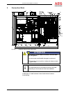
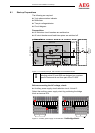
7 Isolating Solar Inverters
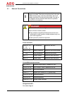
The following are required:
Multimeter
Two-pin voltage detector
Circuit diagram
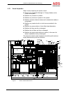
7.1 Isolation Procedure
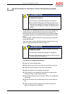
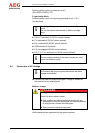
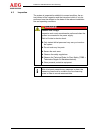
Contact with voltage!
Risk to life due to electric shock.
The capacitors can continue to carry voltage for quite
some time; terminal X11 (AC control cabinet) will also re-
main live.
Switching off Q26 (external) and Q4 does not isolate the
system entirely from the voltage!
The remote signalling lines may still be live even after the
mains and DC have been disconnected!
Only trained skilled personnel may isolate the system.
Do not touch any live parts.
To isolate the system from the voltage, you must dis-
connect the supply lines.
Wear personal protective equipment.
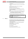
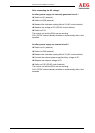
Switch the PV solar inverter off via the DOU.
Switch off Q26 (external).
Switch off F60, F61 (DC/AC control cabinet).
Switch off GCBs (external).
Remove all F41 fuses (DC/AC control cabinet).
Check that there is no voltage at X41 and X3 (DC/AC control
cabinet).
Observe the "five rules of safety", i.e. "earth and short-circuit"
the AC and DC supplies if necessary.
DANGER