


Protect PV.630 Installation and Start-up
16 of 21 80000047963 BAL
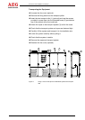
Check the cables to ensure the polarity and phase sequence
are correct.
Remove any cable debris, tools, bolts, etc. from the connection
panel.
Replace the partition plates in the floor of the cabinet.
Reattach the connection cover.
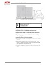
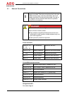
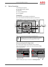
Connection of the control and signal lines
The control and signal lines for remote signalling are connected
using a 3 mm screwdriver.
Shielded control and signal lines may be advantageous in terms of
EMC.
For this purpose, connect the shield of the lines to the terminal
unit. Additionally, the shield can be connected to the PE con-
nection provided on the control unit pivot plate.
Correct routing of the PE conductor acc. to IEC 60364-5-54.
i
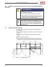
The cable clamp rail is located 130 mm above the floor.
Observe the bending radius!
(With one bend: radius = 10 x diameter)
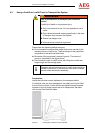
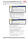
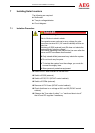
6 Start-up
Special AEG Power Solutions software and hardware tools must
be used for initial start-up. Only skilled personnel trained by AEG
Power Solutions are in a position to use these tools correctly and
to perform initial start-up.
Once the system has been fully installed, the following aspects
must be checked:
Screw connections properly tightened
Connection cables correct
Tool removed
Terminal space covers attached
Read the operating instructions prior to start-up.