


Protect PV.630 Operating Instructions
8000047961 BAL 49 of 72
LED signals:
Green/red flashes: Configuration can be selected via the ter-
minal
(up to 30 seconds after restarting)
Green on: Operating status; no external communica-
tion via X2 and X5
Green flashes: Data transmission on the serial interfaces
(X2 or X5)
Red on: Fault
Description of serial interfaces:
Port 1: Serial interface X2
The potential-free RS232 serial interface at connector X2 supports
the AEG-specific CBSER protocol for parameter setting and moni-
toring purposes. Special service tools can be used to monitor and
manage the equipment locally and (with the aid of the COM serv-
er) remotely via a network. This is also the port used for configur-
ing the assembly's interfaces.
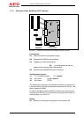
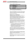
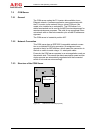
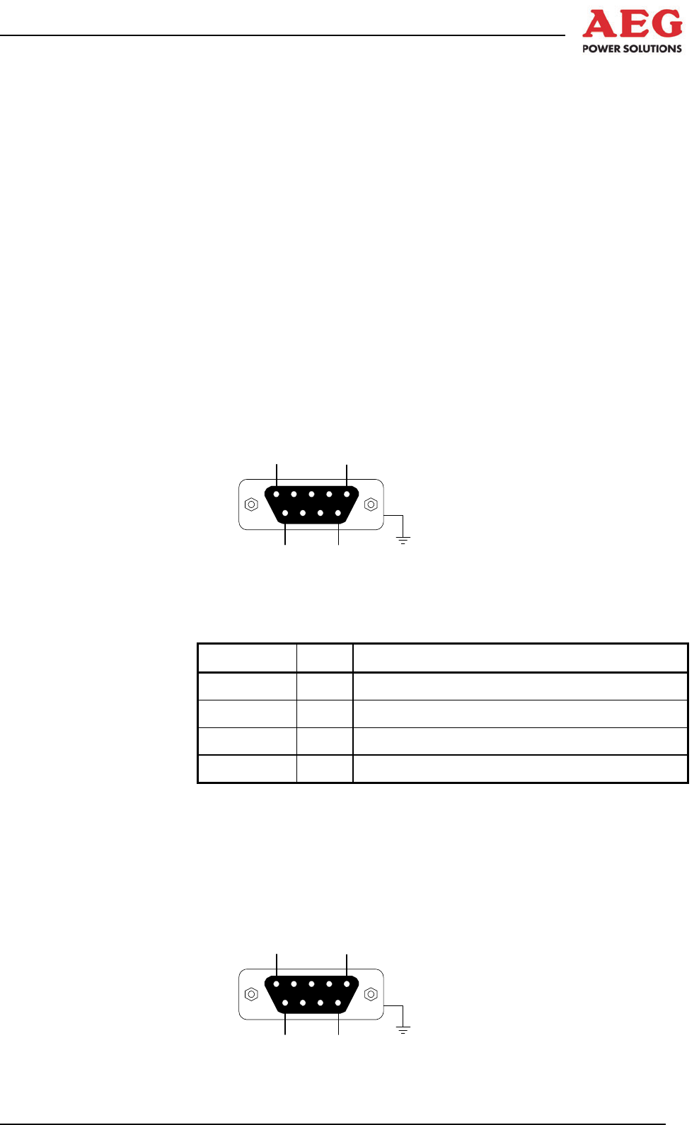
1
5
6
9
Figure 14 Serial D-sub connector X2
Port 1 (X2): RS232 pin assignment
Pin number Signal Description
2 RxD PC receiving data from the MCC
3 TxD PC sending data to the MCC
5 GND Interface reference potential
Housing INV housing potential
Please use a 1:1 data cable for configuration purposes.
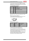
Port 2: Serial interface X5
The potential-free RS485 interface at connector X5 supports the
Modbus protocol for integration into higher-level monitoring sys-
tems.
1
5
6
9