


Protect PV.630 Installation and Start-up
80000047963 BAL 17 of 21
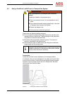
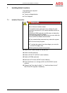
6.1 Start-up Preparations
The following are required:
3-pin phase-rotation indicator
Multimeter
Two-pin voltage detector
Circuit diagram
Prerequisites:
All miniature circuit breakers are switched on.
All circuit breakers and load interrupters are switched off.
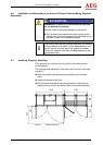
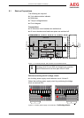
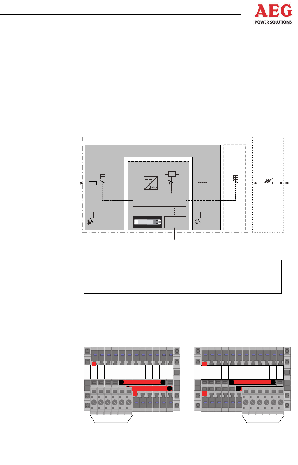
-F41
-Q4.1
-Q1
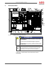
12
Protect PV.
-F13,
-F22,
-F60,
-F61,
-F101
-F38,
-F81
-A1
-K7
-L26
-Q26
Com
Control
DC (PV-Modul)
EVU-Netz
Mains
+DCD/ACD
+INV
+NSHV
Figure 7 - Functional principle, with miniature circuit breakers shown
i
Isolating points Q1 and Q26 are designed on a system-
specific basis and do not form part of the PV.630.
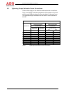
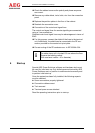
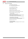
Before connecting the AC voltage, check:
Auxiliary power supply circuit selection circuit 1/circuit 2
Select the auxiliary power supply circuit by positioning the bridge
block on terminal X14.
11223 3445566778899
1
0
1
0
1
1
1
1
1
2
1
2
X14
X14
12
Figure 8 – Auxiliary power supply circuit selection 1 left bridge block: