


Protect PV.630 Operating Instructions
8000047961 BAL 15 of 72
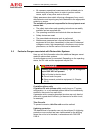
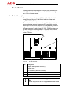
System stop switch
The system stop switch is on the door of the equipment's DC/AC
control cabinet.
The system stop switch is not intended for switching off the equip-
ment. It may only be used in an emergency.
The DOU is used, amongst other things, to switch the equipment
on and off.
The system stop switch causes the
- PV inputs
- mains input and
- mains 2 input
to be separated. This interrupts the energy supply.
It does not mean that the unit has been de-energised!
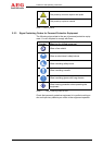
2.6 Safety Signs and Warning Notices on the Equipment
Safety signs and warning notices are located in the vicinity of dan-
ger spots. They provide information about electrical hazards and
residual hazards associated with working on and with the equip-
ment.
Safety signs and warning notices must always be in perfect condi-
tion and clearly legible. You must comply with safety signs and
warning notices whenever you are working on or with the equip-
ment.
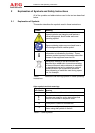
2.7 Safety and Protection Devices for the Equipment
This section describes all safety and protection devices. Safety
and protection devices protect personnel against hazards which
cannot be countered by safe design.
Safety and protection devices must always be in perfect working
order.
2.7.1 Protective Covers
The equipment is designed so that the live components in the op-
erating area are secured with protective covers wherever possible.
The protective covers provide protection against accidental contact
with live parts.
Such protection may only be removed for start-up and for mainte-
nance or repair work.
The covers must be replaced immediately on completion of such
work and checked to ensure that they are in perfect working order.