


Protect PV.630 Operating Instructions
60 of 72 8000047961 BAL
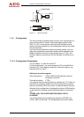
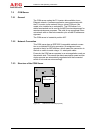
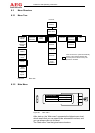
X7: Connection to MultiCom interface
S1: Service switch
X3: When a signal is received, the contact between the two
contact points with the lower numbers is closed (normal-
ly open or “NO”).
X4: When a signal is received, the contact between the two
contact points with the lowest numbers is open (normally
closed or “NC”).
X5: The control signal is active when the input is bridged
(normally open). The inverter is switched off.
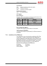
The following default signals are used for remote signalling:
X3.1-2 3 Inverter feed operation (NO)
X3.4-5 6 DC distribution signal* (NO)
X3.7-8 9 AC distribution signal* (NO)
X3.10-11 12 Incoming mains fault (NO)
X4.1 2-3 Inverter fault* (NC)
X5.1-2 Inverter remote switch-off (NO)
*): Collective signals that contain all messages and faults
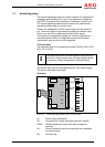
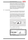
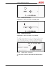
Figure 23 shows the normally closed contact in the state that ap-
plies when the signal is not active (normally open) or the voltage is
zero.
The service switch enables maintenance work on the unit to be
signalled to the MultiCom interface using various protocols.