


Protect PV.630 Operating Instructions
52 of 72 8000047961 BAL
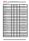
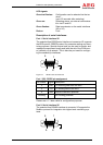
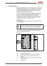
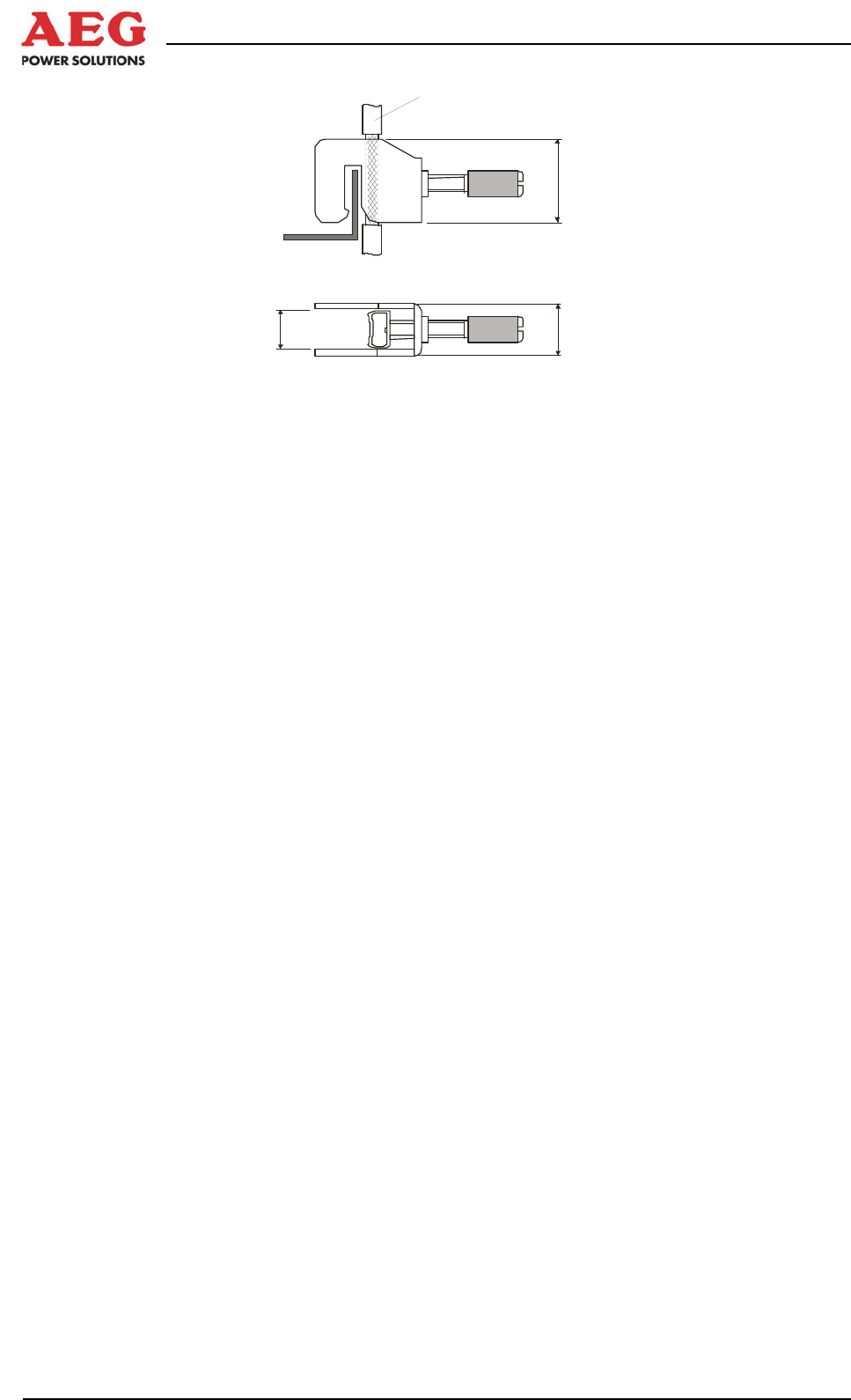
9,5
12
19,5
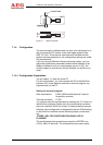
Kabel/Cable
Figure 17 Shield connection
7.1.4 Configuration
The communication interface does not have to be configured in or-
der to connect the PV inverter to the data logger system of the
AEG “PV.LoG”. Once the bus cable has been installed and the
system has been powered up, the configuration settings are made
fully automatically.
If you are using a different/in-house monitoring system, you can
adjust the transmission parameters and the slave address of the
Modbus interface to suit your requirements via port 1 (X2). We
would be happy to provide you with the Modbus unit profile on re-
quest.
7.1.4.1 Configuration Preparations
You will need a 1:1 data line and a PC.
For this configuration, you must connect the PC to the MultiCom
interface (X2) via the data line and start a terminal program, e.g.
Hyperterminal, on the PC.
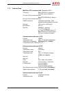
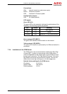
Setting the terminal program:
Data transmission: COMx, 9600 baud/8 data bits/1 stop bit
No parity/no protocol
Terminal emulation: VT100
You can then start the configuration by pressing the “S1” button on
the MultiCom interface. Ensure that no communication has taken
place via interfaces X2/X5 for at least 10 seconds before doing so.
Initiation of the configuration is displayed by the two LEDs flashing
on the MultiCom interface and the following display on the termi-
nal:
“PRESS <CR> FOR CONFIGURATION WHILE LED IS
FLASHING”
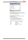
The configuration starts provided you press the <ENTER> key
(<CR>) within 30 seconds. The configuration main menu opens: