


Protect PV.630 Installation and Start-up
6 of 21 80000047963 BAL
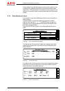
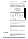
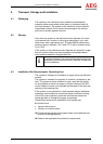
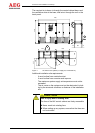
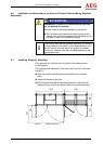
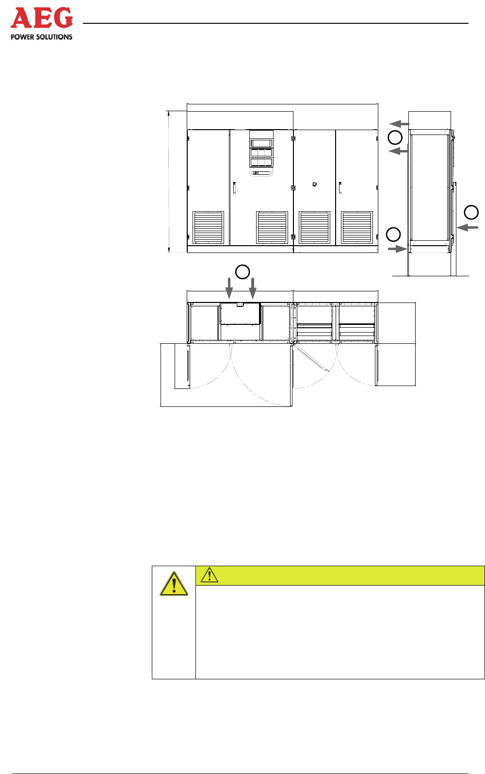
The required air is drawn in through the control cabinet doors and
the ventilation slots at the base, and let out through the roof or the
back panel.
2
0
7
0
660
925
1500
1200
75
600
625
60011,5
2700
1
1
1
2
Figure 1 Air vents on the system (1=supply air, 2=exhaust air)
Additional installation site requirements:
- It must be free from conductive dust
- It must be free from corrosive acid vapours
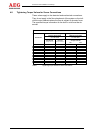
- The maximum system supply air temperature must not be
exceeded
- The air vents on the system must not be obstructed, includ-
ing by the structural conditions or features of the installation
site.
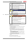
Risk of injury due to rotating fans!
The fans of the INV control cabinet are freely accessible.
Never reach into rotating fans.
When setting up any system, ensure that the fans can-
not be touched.
CAUTION