


Protect PV.630 Operating Instructions
8000047961 BAL 51 of 72
The X5 interface can be switched from RS485 to RS232 using
jumpers J4 and J5. The factory setting is RS485, i.e. all jumpers
are inserted at J4. You have the option of switching the interface to
RS232 by reconnecting all jumpers to J5.
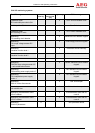
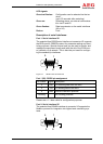
Port 2 (X5): RS232 pin assignment
Pin number Signal Description
2 RxD PC receiving data
3 TxD PC sending data
5 GND Interface reference potential
7 RTS Handshake
8 CTS Handshake
Housing INV housing potential
If the RS232 version is used for this port, please use a 1:1 data
line.
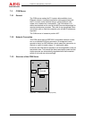
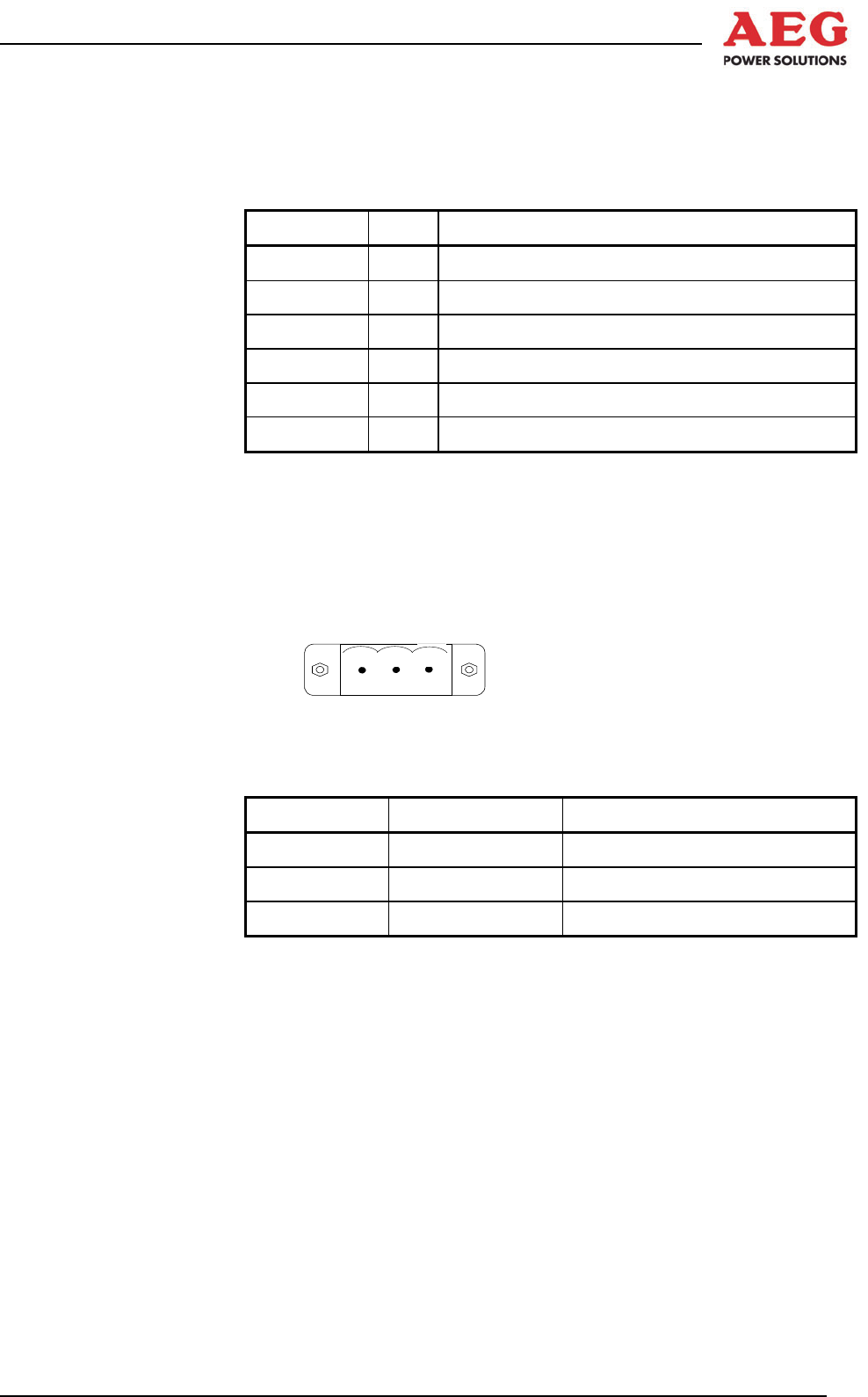
Controller Area Network (CAN) at X4
Up to four remote panels can also be connected to the potential-
free CAN interface for central signalling and display.
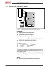
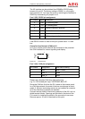
1
Figure 16 Connector X4
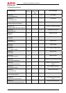
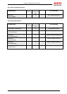
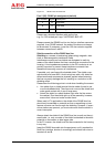
Port 3 (X4): CAN pin assignment
Pin number Designation Cable colour coding
1 GND White + brown
2 Data_L Yellow
3 Data_H Green
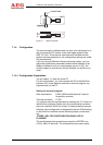
Please use a shielded CAN bus cable as the line,
e.g. 2 x 0.22 twisted pair Lapp “UNITRONIC-BUS LD”.
Route the CAN bus line from the PV inverter to the remote panel.
In a CAN bus network, the ends of the bus must always be termi-
nated. A 120 ohm terminating resistor is pre-installed at connector
X4 of the CAN bus connection as standard.
Connect the line shield to the housing potential of the INV unit via
shield terminal blocks. Openings are provided in the plate of the
PV inverter for installing the shield in the connection room area.
Remove approx. 20 mm of the sheath at this point.