


Protect PV.630 Operating Instructions
8000047961 BAL 71 of 72
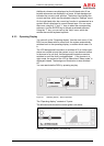
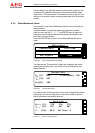
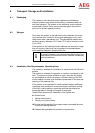
You can use the “Inverter” menu item to display the statuses and
measured values for the inverter. You can toggle between the two
menus using the “>” and “<” keys.
In normal operation, the inverter can be switched on and off here,
using the top key. In the event of a deactivating fault, you can call
up a detailed description of the fault here. Once the fault has been
rectified, you will need to acknowledge it using the top key. A high-
voltage symbol “V” will then appear on the top key.
-- Iverter-Status --
Grid operation MPP
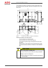
-- Inverter-data --
U
L12-31
.[V]: 270 270 270
I
L1-3
..[A]: 587 587 587
P....[kW]: 261 S...[kVA]: 275
Q..[kvar]: 14 cos(phi).: 275
F....[Hz]: 50.0 E...[kWh]: 937
T
1
...[°C]: 25.0 T
2
...[°C]: 28.0
E
..[kWh]: 2089336
t
....[h]: 1262
Figure 42 Menu: Inverter
The voltage and current of the three phases are displayed as
measured values. The power values P, S, Q and cos-phi appear
underneath these voltages and currents.
These are then followed by the frequency F and the daily energy
E.
The ambient temperature of cabinet T1 and the supply air temper-
ature of inverter stack T2 are shown as the temperatures.
Next come the total energy counter ∑E and the inverter operating
hours counter ∑t.
You can scroll through the measured values using the “v” and “^”
keys.
You can use the “COM interface” menu item to look up the status-
es of the communication PCBs.
You can use the “AUX signals” menu item to look up the status of
optional general signals on the remote signalling board.
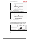
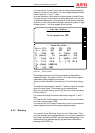
8.3.5 Blocking
You can call up the “Blocking” menu from the “Main menu”. After
you have entered the current password, you can block operation of
the inverter (switching ON/OFF and fault acknowledgement). The
password must be entered digit by digit and then confirmed by
pressing the ENTER key.