


DEFINITY Enterprise Communications Server Release 6
Installation and Test for Compact Modular Cabinets
555-230-128
Issue 3
May 1998
Install and Cable the Cabinets
Page 1-93Install Emergency Transfer Unit and Associated Telephones
1
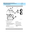
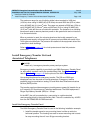
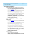
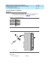
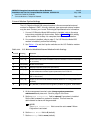
9. Check the system for emergency transfer operation as follows:
a. Place the test switch (switch 12) in the ACTIVATED position.
b. The power LED should be OFF.
c. Verify there is dial tone on all emergency transfer sets.
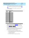
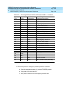
15 S-BK RLC4 Ring-PBX Line Port 4
41 Y-BL TST4 Tip-Emergency Terminal 4
16 BL-Y RST4 Ring-Emergency Terminal 4
42 Y-O TTC5 Tip-PBX Trunk Circuit 5
17 O-Y RTC5 Ring-PBX Trunk Circuit 5
43 Y-G TTK5 Tip-CO Trunk Circuit 5
18 G-Y RTK5 Ring-CO Trunk Circuit 5
44 Y-BR TLC5 Tip-PBX Line Port 5
19 BR-Y RLC5 Ring-PBX Line Port 5
45 Y-S TST5 Tip-Emergency Terminal 5
20 S-Y RST5 Ring-Emergency Terminal 5
46 V-BL COM1 Common 1 Relay Contact
21 BL-V NO1 Normally Open 1 Contact
47 V-O NC2 Normally Closed 2 Contact
22 O-V NC1 Normally Closed 1 Contact
48 V-G COM2 Common 2 Relay Contact
23 G-V NO2 Normally Open 2 Contact
49 V-BR
24 BR-V
50 V-S GRD Ground From PBX
25 S-V -48PX -48V from Alarm Panel (AUX Cable)
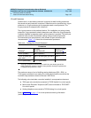
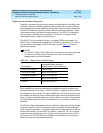
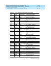
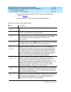
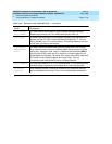
Table 1-17. Pin Assignments for 25-Pair Connector on 808A — Continued
Pin Color Designation Connector/Description
Continued on next page