


DEFINITY Enterprise Communications Server Release 6
Installation and Test for Compact Modular Cabinets
555-230-128
Issue 3
May 1998
Installation Completion and Cable Pinouts
Page 2-4Installation Completion
2
Installation Completion
1. Enter logoff and press Enter to prevent unauthorized changes to data.
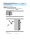
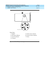
2. Set the left and right doors onto the hinge pins and close the doors. The
doors must be closed to prevent EMI emissions. Tighten the door screws.
3. Set the right cover panel onto the right panel and secure. Do not use
force.
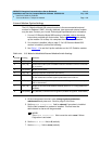
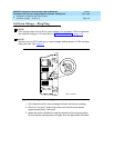
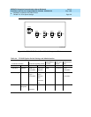
Power Supply LED Indications
It is not possible to view the alarm log to determine which power unit in a
multi-cabinet system is defective. Use the LEDs on the front of each power unit to
determine its state.
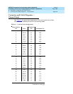
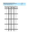
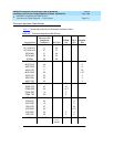
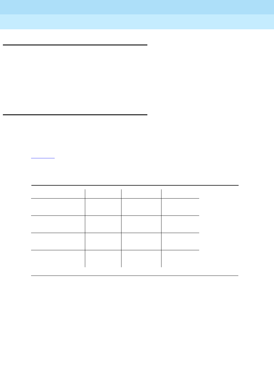
Tab le 2 - 1
shows the LED and alarm conditions. Ring voltage and neon bus
output do not activate alarm status.
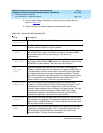
Table 2-1. LED and Alarm Conditions
Condition LED Status Alarm State Fan Alarm
Normal Red off
Yellow on
open high
No Input Power Red off
Yellow off
closed open
Any DC Output
not Present
Red on
Yellow off
closed no state
Fan Alarm Red on
Yellow off
closed low