


DEFINITY Enterprise Communications Server Release 6
Installation and Test for Compact Modular Cabinets
555-230-128
Issue 3
May 1998
Installation Completion and Cable Pinouts
Page 2-9Connector and Cable Diagrams — Pinout Charts
2
Connector and Cable Diagrams —
Pinout Charts
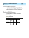
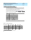
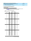
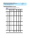
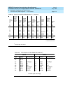
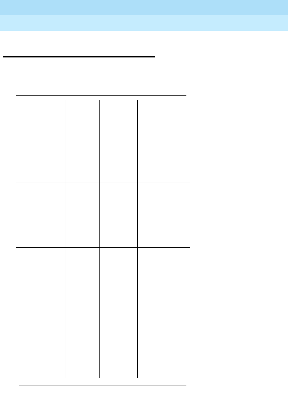
See Ta b le 2 - 6 for typical lead designations. The circuit packs and auxiliary
equipment are classified as shown in the following tables.
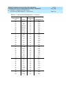
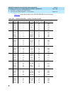
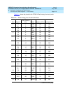
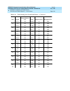
Table 2-6. Lead and Color Designations
Cross-Connect
Pin Color
Amphenol
Pin Backplane Pin
1W-BL26 102
2 BL-W 01 002
3W-O27 103
4O-W02 003
5W-G28 104
6G-W03 004
7W-BR29 105
8BR-W04 005
9W-SL30 106
10 SL-W 05 006
11 R-BL 31 107
12 BL-R 06 007
13 R-O 32 108
14 O-R 07 008
15 R-G 33 109
16 G-R 08 009
17 R-BR 34 110
18 BR-R 09 010
19 R-SL 35 111
20 SL-R 10 011
21 BK-BL 36 112
22 BL-BK 11 012
23 BK-O 37 113
24 O-BK 12 013
Continued on next page