


DEFINITY Enterprise Communications Server Release 6
Installation and Test for Compact Modular Cabinets
555-230-128
Issue 3
May 1998
Installation Completion and Cable Pinouts
Page 2-20
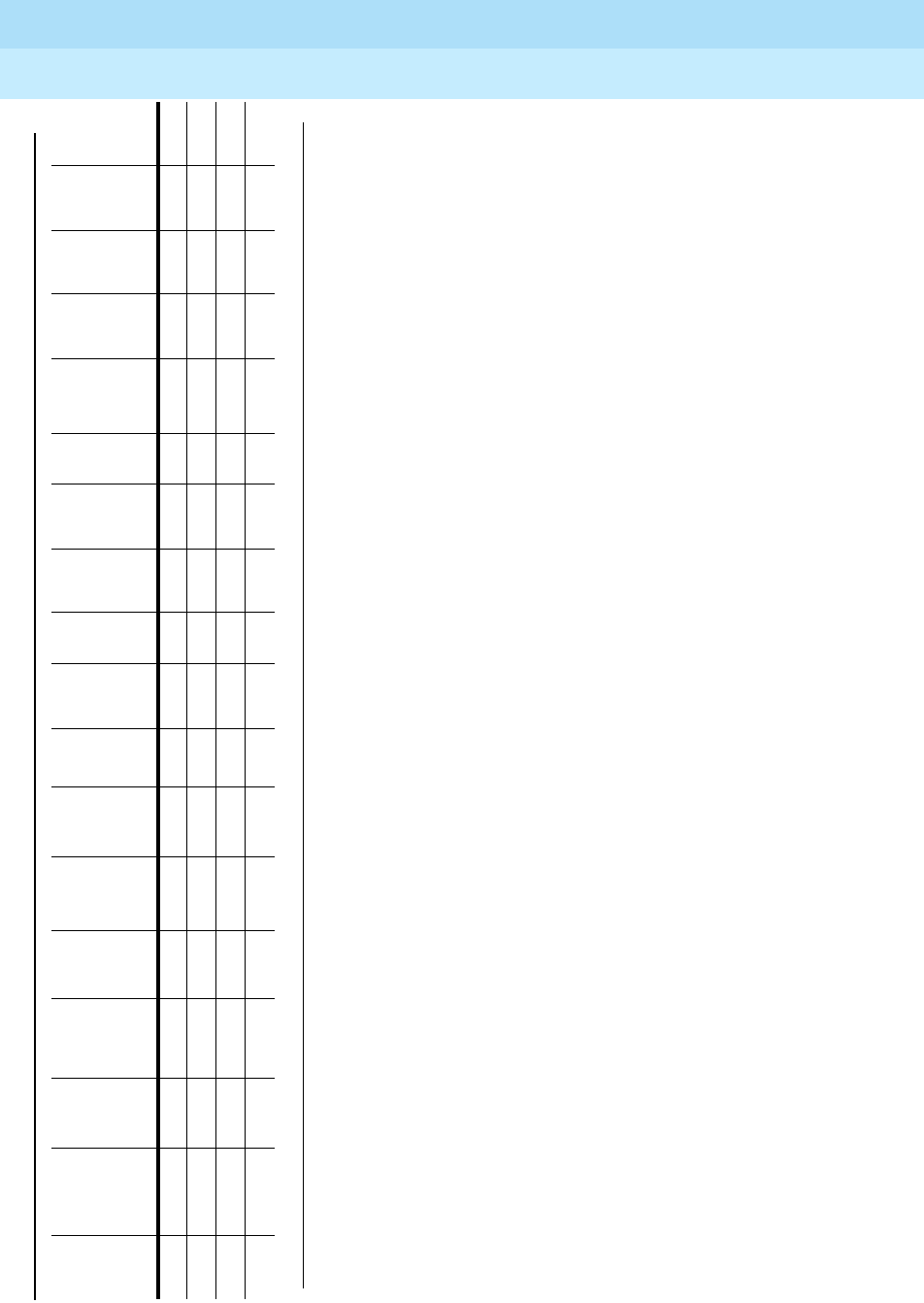
2
†
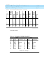
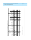
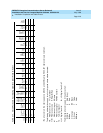
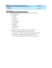
The wire colors in this chart apply only to B25A and A25B cables. H600-307 cable colors are not shown.
The following abbreviations apply for all circuit packs unless otherwise noted:
T,R PBX transmit voice T Tip (A) Green
T1,R1 PBX receive voice R Ring (B) Red
M PBX transmit signal S Sleeve
E PBX receive signal PX PBX transmit
TX Terminal transmit
LI, LI* Digital Trunk IN LO, LO* Digital Trunk OUT
The following wire colors apply in the above chart:
W White S Slate (Grey)
BLBlue R Red
O Orange BK Black
G Green Y Yellow
BRBrown V Violet
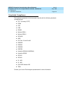
V-BR 49 T16 PXT8 T24 P-8 LBACK2 TXT12 PXT12
BR-V 24 R16 PXR8 R24 P+8 LBACK1 TXR12 PXR12
V-S 50
S-V 25
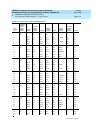
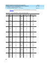
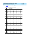
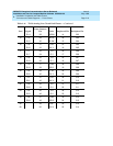
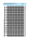
Table 2-13. Circuit Pack and Auxiliary Equipment Leads (Pinout Charts)
Color
Connector
Pin
Numbers
Analog
Line
8 ports
2-Wire
Digital
Line and
Analog
Line
16 ports
Data
Line
and
Digital
Line
4-wire
Digital
Line
2-Wire
24 Ports
Hybrid
Line
MET
Line
AUX
Tru nk
CO
Tr k.
CO
Trunk
3-wire
DID/
DIOD
Tr u n k
Tie
Tr k .
DS1
Tie
Trunk
ISDN
BRI
Line
4-wire
ISDN
BRI
Line
2-wire
Packet
Data
Line
Four
Port
DIOD
Continued on next page