


DEFINITY Enterprise Communications Server Release 6
Installation and Test for Compact Modular Cabinets
555-230-128
Issue 3
May 1998
Install and Cable the Cabinets
Page 1-68Telephone Pin Designations
1
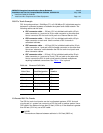
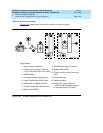
Emergency Transfer and Auxiliary Power
NOTE:
Only 1 emergency transfer power panel and 1 auxiliary power connection is
provided per system.
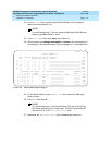
Connect emergency transfer power and auxiliary power as shown in Table 1-12
.
Auxiliary power includes power to an attendant console or adjunct device.
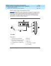
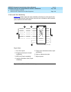
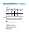
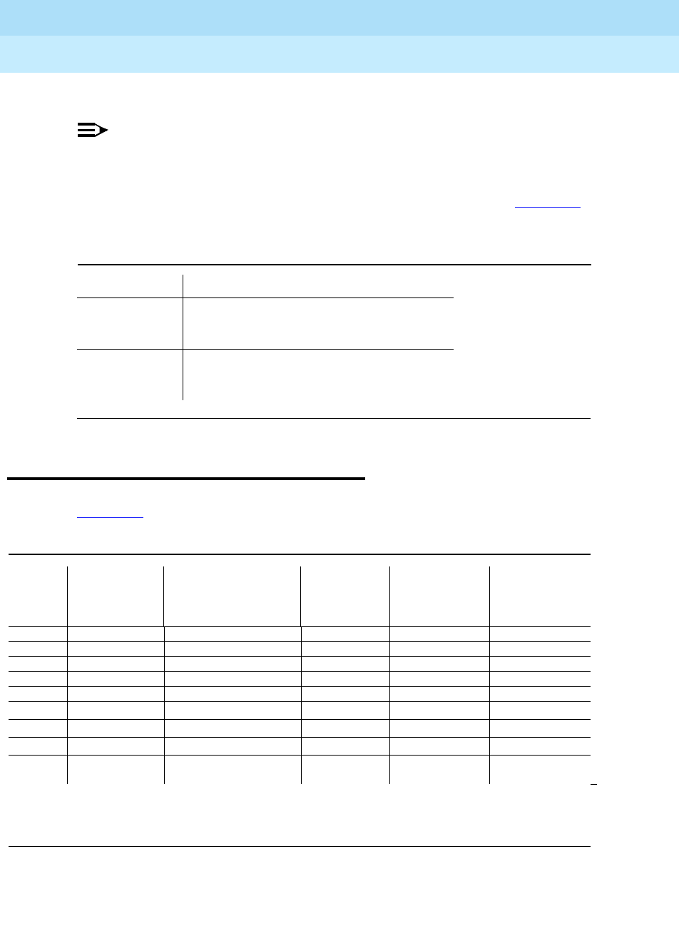
Telephone Pin Designations
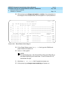
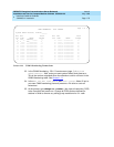
Table 1-13 provides port circuit pack and telephone pin designations.
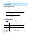
Table 1-12. Emergency Transfer and Auxiliary Power
Color AUX Connector
Black-Blue XFER48 (Emergency Transfer) (Pin 36)
Blue-Black Ground (Pin 11)
Brown-Yellow ACC48A (Adjunct -48 VDC) (Pin 19)
Yellow-Brown Ground (Pin 44)
Table 1-13. Port Circuit Pack and Telephone Pin Designations
Pin on
Modular
Plug
4-wire; 302C1,
8400-Series,
603E, 9403,
9434
2-wire; 302C1,
8400-Series, 603E,
9403, 9410, 9434
8510T BRI
(with adjunct
speaker
phone)
Analog Station,
Modem
Z3A1 & Z3A2
ADU, Data
Module
1TXT TXT
2TXR T TXR
3 PXT TXT R PXT
4TPXR
5RPXT
6PXR TXR PXR
7 -48VDC (-48VDC) (-48VDC)
8 GRD GRD GRD
circuit
pack
4-wire digital
(8 port)
2-wire digital (16 or 24
port)
4-wire BRI
Trunk Side
Analog line (16
or 24 port)
Data Line
PX PBX transmit T Tip (A)
TX Terminal transmit R Ring(B)