


DEFINITY Enterprise Communications Server Release 6
Installation and Test for Compact Modular Cabinets
555-230-128
Issue 3
May 1998
Install and Cable the Cabinets
Page 1-80Install the BRI Terminating Resistor
1
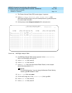
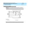
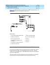
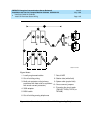
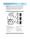
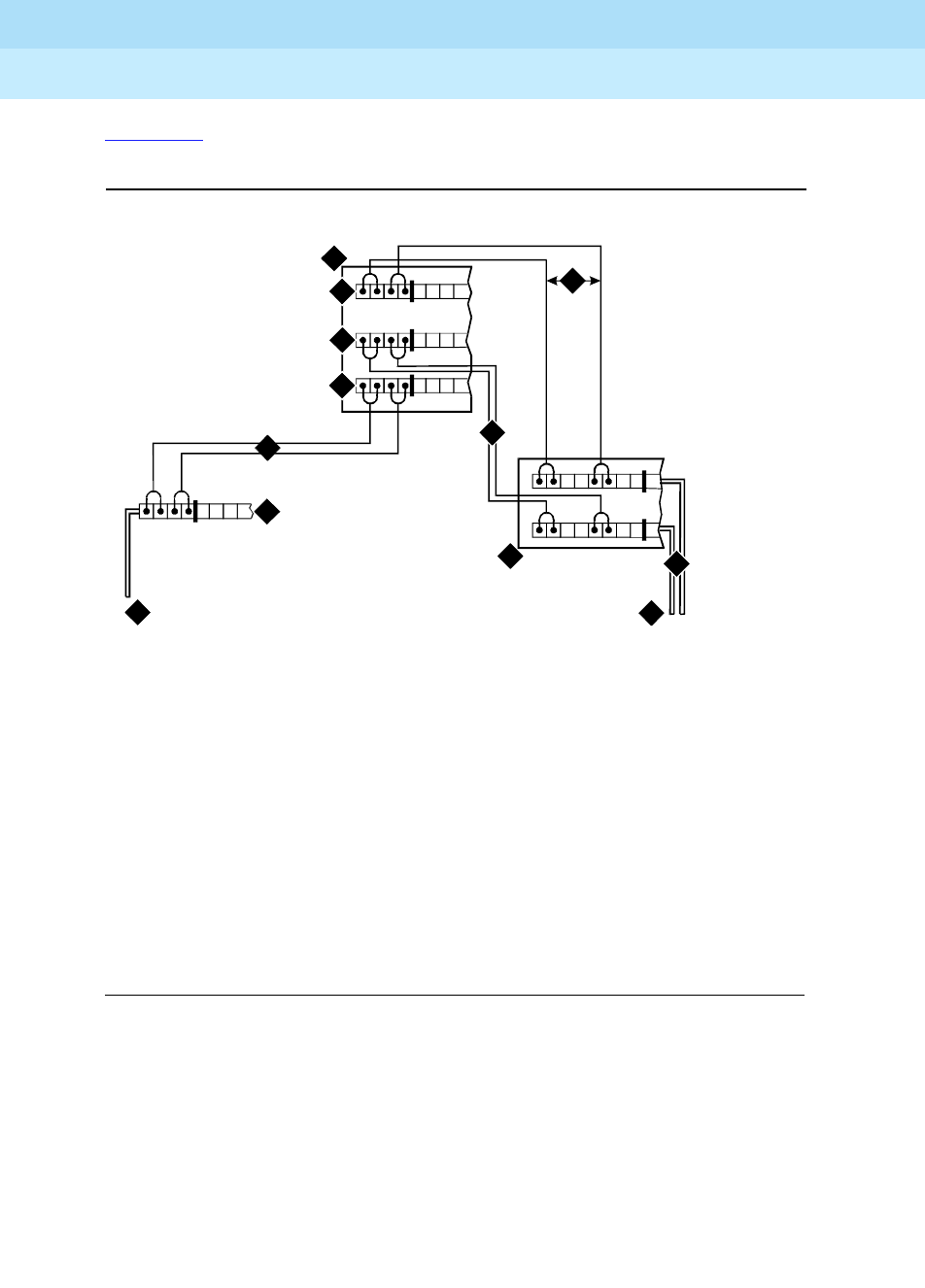
Figure 1-35 shows the wiring connections for the 110RA1-12 terminal block. The
TN556 BRI switch port is terminated to bottom row C.
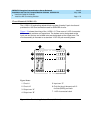
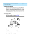
Figure 1-35. Typical Installation of Terminating Resistor Block
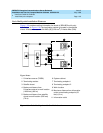
For point-to-point wiring, the top row connects to the blue station field. The pair
connects from the 110RA1-12 to the standard 4-pair circuit. Pair 1 from the
110RA1-12 is connected to Pair 1 of the station field, and Pair 2 is connected to
Pair 3 of the station field.
Two terminal basic multi-point applications are accommodated by connecting
row B (output) to the second terminal common to the multi-point circuit.
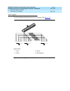
Figure Notes
1. Part of terminating resistor block
2. White or purple field
3. Part of 4-pair blue field
4. From ISDN T-interface circuit
(2-pair)
5. To ISDN S/T-interface terminals
6. 2-pair cross-connect
7. Basic multi-point option
8. 4-pair horizontal cables
9. Row “A”
10. Row “B”
11. Row “C”
TT1RR1
term_blk RPY 012098
3
4
5
1
6
6
2
9
11
7
8
10