DEFINITY Enterprise Communications Server Release 6
Installation and Test for Compact Modular Cabinets
555-230-128
Issue 3
May 1998
Installation Completion and Cable Pinouts
Page 2-19
2
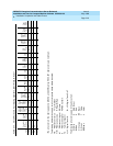
O-BK 12 R8 PXR4 R12 P+4 PXR4 S14 M4 TXR6 R12 PXR6
BK-G 38 T5 T9 T13 V1T5 T5 T5 PXR7 TXT7
G-BK 13 R5 R9 R13 V1R5 R5 R5 PXT7 TXR7
BK-BR 39 T10 TXT5 T14 CT4 TXT7 PXT7
BR-BK 14 R10 TXR5 R14 CR4 TXR7 PXR7
BK-S 40 T11 PXT5 T15 P-5 PXR8 TXT8
S-BK 15 R11 PXR5 R15 P+5 PXT8 TXR8
Y-BL 41 T6 T12 T16 V1T6 T6 T6 TXT8 PXT8
BL-Y 16 R6 R12 R16 V1R6 R6 R6 TXR8 PXR8
Y-O 42 TXT6 T17 CT6 PXR9 TXT9
O-Y 17 TXR6 R17 CR6 PXT9 TXR9
Y-G 43 PXT6 T18 P-6 TXT9 PXT9
G-Y 18 PXR6 R18 P+6 TXR9 PXR9
Y-BR 44 T7 T19 V1T7 T7 T7 PXR10 TXT10
BR-Y 19 R7 R19 V1R7 R7 R7 PXT10 TXR10
Y-S 45 TXT7 T20 CT7 TXT10 PXT10
S-Y 20 TXR7 R20 CR7 TXR10 PXR10
V-BL 46 T13 PXT7 T21 P-7 PXR11 TXT11
BL-V 21 R13 PXR7 R21 P+7 PXT11 TXR11
V-O47T8T14 T22V1T8 T8T8LI*TXT11PXT11
O-V22R8R14 R22V1R8 R8R8LITXR11PXR11
V-G 48 T15 TXT8 T23 CT8 LO PXR12 TXT12
G-V 23 R15 TXR8 R23 CR8 LO* PXT12 TXR12
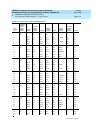
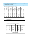
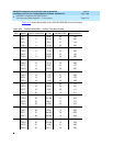
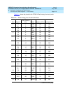
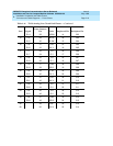
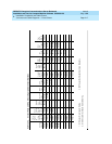
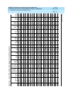
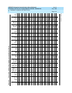
Table 2-13. Circuit Pack and Auxiliary Equipment Leads (Pinout Charts)
Color
Connector
Pin
Numbers
Analog
Line
8 ports
2-Wire
Digital
Line and
Analog
Line
16 ports
Data
Line
and
Digital
Line
4-wire
Digital
Line
2-Wire
24 Ports
Hybrid
Line
MET
Line
AUX
Trunk
CO
Trk .
CO
Trunk
3-wire
DID/
DIOD
Trunk
Tie
Trk .
DS1
Tie
Tr u nk
ISDN
BRI
Line
4-wire
ISDN
BRI
Line
2-wire
Packet
Data
Line
Four
Port
DIOD
Continued on next page


