


DEFINITY Enterprise Communications Server Release 6
Installation and Test for Compact Modular Cabinets
555-230-128
Issue 3
May 1998
Installation Completion and Cable Pinouts
Page 2-11Connector and Cable Diagrams — Pinout Charts
2
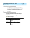
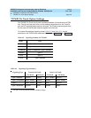
Processor Interface Cable Pinout
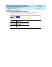
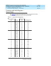
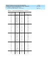
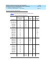
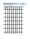
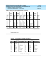
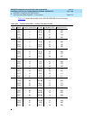
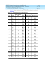
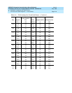
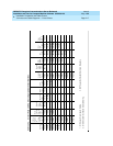
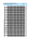
Table 2-7 shows the pinout for the Processor Interface Cable.
Table 2-7. Processor Interface Cable Pinout
Signal Name
Processor (P1)
(Amphenol
Connector) AUX (J1)
TERM
(J3)
DCE
(J2)
Modem
(P2)
ACC48A 40 19
AP1 (alarm in) 2 26
AP2 (alarm in) 27 27
EXTALMA 5 48
EXTALMB 30 23
XFER48 38 36
MOD-CTS 21 5
MOD-DCD 46 8
MOD-DSR 8 6
MOD-DTR 7 20
MOD-GRD 20 1 & 7
MOD-RTS 34 4
MOD-RXD 33 3
MOD-TXD 45 2
TERM-CTS 9 5
TERM-DTR 47 20
TERM-GRD 35 1 & 7
TERM-RXD 10 3
TERM-TXD 22 2
CDR-CTS 49 5
CDR-DCD 24 8
CDR-DSR 12 6
CDR-DTR 37 20
CDR-GRD 23 1 & 7
CDR-RXD 36 3 3
CDR-TXD 48 2 2
GRD 25, 50 1-7,
11-17,
44-46
1, 7 1, 7 1, 7
Continued on next page