


DEFINITY Enterprise Communications Server Release 6
Installation and Test for Compact Modular Cabinets
555-230-128
Issue 3
May 1998
Install and Cable the Cabinets
Page 1-77Install the BRI Terminating Resistor
1
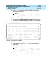
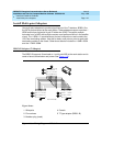
Install the BRI Terminating Resistor
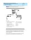
The resistors balance the cable plant between the receiver and the transmitter on
the interface. When using the TN2198 ISDN-BRI 2-Wire U Interface circuit pack,
an NT1 is required. A terminating resistor is always required near the terminal
when the BRI S-type interface circuit pack (TN556 BRI 4-Wire S-NT Line circuit
pack) is used (see
#5ESS Switch Integrated Services Digital Network Customer
Premises Planning Guide
, 533-700-100).
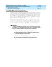
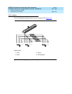
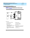
The resistor is built into the NT1 and can be 1 of 3 values, depending on the
configuration and the distance from the NT1 to the ISDN terminal. The resistor
value is controlled from the NT1. A terminating resistor adapter may be needed
near the terminal and can be placed in the satellite closet or work location.
!
CAUTION:
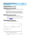
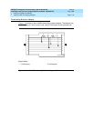
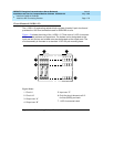
The 440A4 terminating resistor and 110RA1-12 terminating resistor block
are UL listed. Most new installations are the 110RA1-12 terminating resistor
block. The following installation instructions should be observed.
■
Never install telephone wiring during a lightning storm.
■
Never install telephone jacks in wet locations unless the jack is
specifically designed for wet locations.
■
Never touch uninsulated wires or terminals unless the telephone
line has been disconnected at the network interface.
■
Use caution when installing or modifying telephone lines.