


DEFINITY Enterprise Communications Server Release 6
Installation and Test for Compact Modular Cabinets
555-230-128
Issue 3
May 1998
Install and Cable the Cabinets
Page 1-67Connect External Alarms and Auxiliary Connections
1
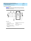
Connect External Alarms and
Auxiliary Connections
NOTE:
The AUX connector is part of the Processor Interface cable assembly (J1).
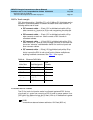
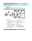
Alarm Input
Alarms can be generated on adjunct equipment, sent to the DEFINITY System,
and recorded and reported as “external alarms.” A typical major alarm
input
is
from a UPS.
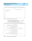
1. Connect 1 major and 1 minor alarm
input
pair to the trunk/auxiliary field
from the AUX connector (J1 on Processor Interface Cable). See Ta b l e
1-10.
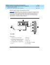
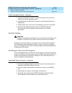
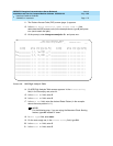
Alarm Output
The system provides a relay contact that can operate a customer-provided
alarm, such as a light or bell. The circuitry and power source are customer-
provided. The alarm device must not exceed a rating of more than 30 VAC RMS
or 60 VDC at 0.75 Amps.
1. Connect the external alarm
output
. See Table 1-11.
2. Give this information to your Lucent Technologies representative for
troubleshooting purposes.
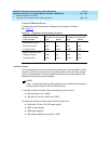
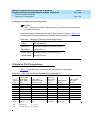
Table 1-10. Alarm Inputs at AUX Connector
Color AUX Connector
White-Blue AP1 (Pin 26) Major Alarm Input
Blue-White Ground (Pin 1)
White-Orange AP2 (Pin 27) Minor Alarm Input
Orange-White Ground (Pin 2)
Table 1-11. Alarm Output at AUX Connector
Color AUX Connector
Violet-Green EXTALMA (Pin 48) Alarm Output
Green-Violet EXTALMB (Pin 23) (Ground) Alarm Output