


DEFINITY Enterprise Communications Server Release 6
Installation and Test for Compact Modular Cabinets
555-230-128
Issue 3
May 1998
Install and Cable the Cabinets
Page 1-26Install Main Distribution Frame and External Modem
1
Install Main Distribution Frame and
External Modem
Install the MDF
!
CAUTION:
The optional MDF is a special 110 cross-connect field and is smaller than standard
110 cross-connect hardware. Do not install standard 110 hardware inside the right
panel.
NOTE:
The depth of any equipment installed inside the right panel must not exceed 2.5
inches (6.3 cm), otherwise the right cover panel cannot fit over the right panel.
The optional MDF represents the trunk/auxiliary field.
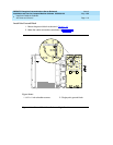
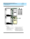
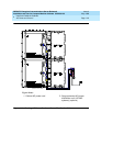
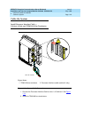
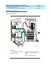
1. Mount the optional MDF to the right panel. See Figure 1-16
. The MDF may
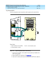
be mounted at the top of the right panel in other cabinets, if desired. See
Figure 1-17
.
Install the External Modem
The U.S. Robotics Model 839 external modem is the recommended external
modem. Release 6 CMC systems operate with this modem set to the factory
default settings.
NOTE:
You may use a locally obtained, type-approved external modem (33.6 bps
and V.34 protocol). Contact your Lucent Technologies representative for
more information.
1. Use installer-provided hardware to mount the modem. See Figure 1-16
.
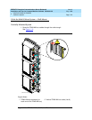
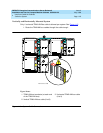
2. Route the MODEM cable (P2) from the Processor Interface Cable through
the cable trough and to the modem.
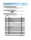
3. Connect the cable to the modem. Refer to ‘‘
Processor Interface Cable
Pinout’’ on page 2-11 for the pinout of the modem cable.
4. Plug the modem power cord into an electrical outlet and turn on the
modem.
5. Modem setup and administration is performed in ‘‘
External Modem Option
Settings’’ on page 1-98.