


DEFINITY Enterprise Communications Server Release 6
Installation and Test for Compact Modular Cabinets
555-230-128
Issue 3
May 1998
Install and Cable the Cabinets
Page 1-96Install Emergency Transfer Unit and Associated Telephones
1
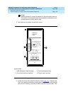
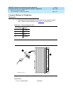
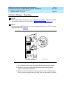
Install Telephone for Power Transfer Unit
Trunk/Auxiliary Field: Telephone Used Only for Emergency Transfer
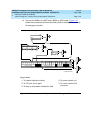
1. Connect a pair of wires between the -48V and GRD terminals on the yellow
emergency transfer row/connecting block and the EM TRANS RELAY PWR
terminal. See Figure 1-42
.
2. Connect CO trunk leads from the purple field to the TC terminals on the
yellow emergency transfer row/connecting block for each trunk.
3. Connect CO trunk leads from the green field to the TK terminals on the
yellow emergency transfer row/connecting block for each trunk.
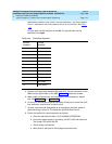
4. Connect the ST leads on the yellow emergency transfer row/connecting
block for each emergency transfer telephone to the ST terminal
appearance in the yellow trunk/auxiliary field. The ST terminal leads
should be terminated on the following pairs: 1, 4, 7, 10, 13, 16, 19, or 22
(the first pair of any 3-pair group).
5. Connect the ST leads from the terminal in Step 4 to the assigned terminal
in the blue or white station distribution field.
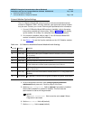
Trunk/Auxiliary Field: Telephone Used for Emergency Transfer and as
Normal Extension
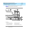
1. Connect a pair of wires between the -48V and GRD terminals on the yellow
emergency transfer row/connecting block to the EM TRANS RELAY PWR
terminal. See Figure 1-43
.
2. Connect CO trunk leads from the purple field to the TC terminals on the
yellow emergency transfer row/connecting block for each trunk.
3. Connect CO trunk leads from the green field to the TK terminals on the
yellow emergency transfer row/connecting block for each trunk.
4. Connect telephone leads from the purple analog line board row/
connecting block to the LC terminals on the yellow emergency transfer
row/connecting block for each telephone.
5. Connect ST leads on the yellow emergency transfer row/connecting block
for each emergency transfer telephone to the ST terminal appearance in
the purple trunk/auxiliary field.
6. Connect the ST leads from the terminal in Step 5 to the assigned terminal
in the blue or white station distribution field.
Telephone Installation
1. Connect the telephone to the information outlet.
2. Install patch cords/jumper wires between the system side and the station
side of the station distribution field on the MDF.