


DEFINITY Enterprise Communications Server Release 6
Installation and Test for Compact Modular Cabinets
555-230-128
Issue 3
May 1998
Install and Cable the Cabinets
Page 1-89Install Emergency Transfer Unit and Associated Telephones
1
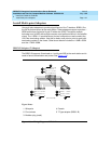
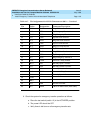
The maximum range for out-of-building digital voice terminals is 3400 feet
(1036 m) when using 24 AWG (#5) (0.26 mm
2
) wire and 2200 feet (670 m) when
using 26 AWG (#4) (0.14 mm
2
) wire. The range can extend to 5000 feet (1524 m)
using 24 AWG (#5) (0.26 mm
2
) wire or 4000 feet (1219 m) using 26 AWG (#4)
(0.14 mm
2
) wire with the use of a data link protector. The protector is an isolating
transformer used to remove phantom power on the system side and re-introduce
it on the terminal side.
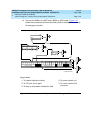
When a protector is used, the voice terminal must be locally powered by an
external power supply or through the AC power cord provided with some of the
7400-type voice terminals. The protector is installed on the equipment side of the
protection in both buildings.
Refer to Table 1-1 on page 1-3
for circuit protector and data link protector
comcodes.
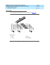
Install Emergency Transfer Unit and
Associated Telephones
NOTE:
Install only 1 emergency transfer power panel per system.
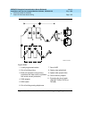
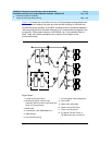
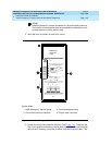
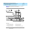
Emergency transfer capability is provided by an 808A Emergency Transfer Panel
(or equivalent) mounted next to the trunk/auxiliary field. See Figure 1-41
. Also
refer to Table 1-12 on page 1-68
for the pinout of the AUX (J1) connector.
Use analog telephones for emergency transfer. The 500-and 2500-type
telephones can also be used as normal extensions. Emergency transfer
capability may be provided on analog CO and Wide Area Telecommunications
Service (WATS) trunks.
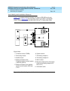
The transfer panel provides emergency trunk bypass or power-fail transfer for up
to 5 incoming CO trunk loops to 5 selected station sets. The 808A equipment’s
Ringer Equivalency Number (REN) is 1.0 Amp.
At the MDF, the unit is controlled by a connection to a yellow terminal
row/connecting block in the trunk/auxiliary field. The unit is controlled by -48 VDC
from the EM TRANS RELAY PWR terminals.
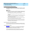
Install the Emergency Transfer Panel
The 808A Emergency Transfer Panel is used in the following installation example.
1. Install the transfer panel on any mounting frame in either a vertical or
horizontal position. The housing has ears for screw-mounting and cutouts
for snap-mounting the unit in an 89-type mounting bracket.