


DEFINITY Enterprise Communications Server Release 6
Installation and Test for Compact Modular Cabinets
555-230-128
Issue 3
May 1998
Install and Cable the Cabinets
Page 1-64Install and Wire Telephones and Other Equipment
1
Adjunct Power Connections
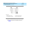
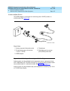
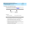
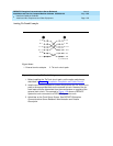
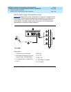
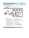
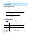
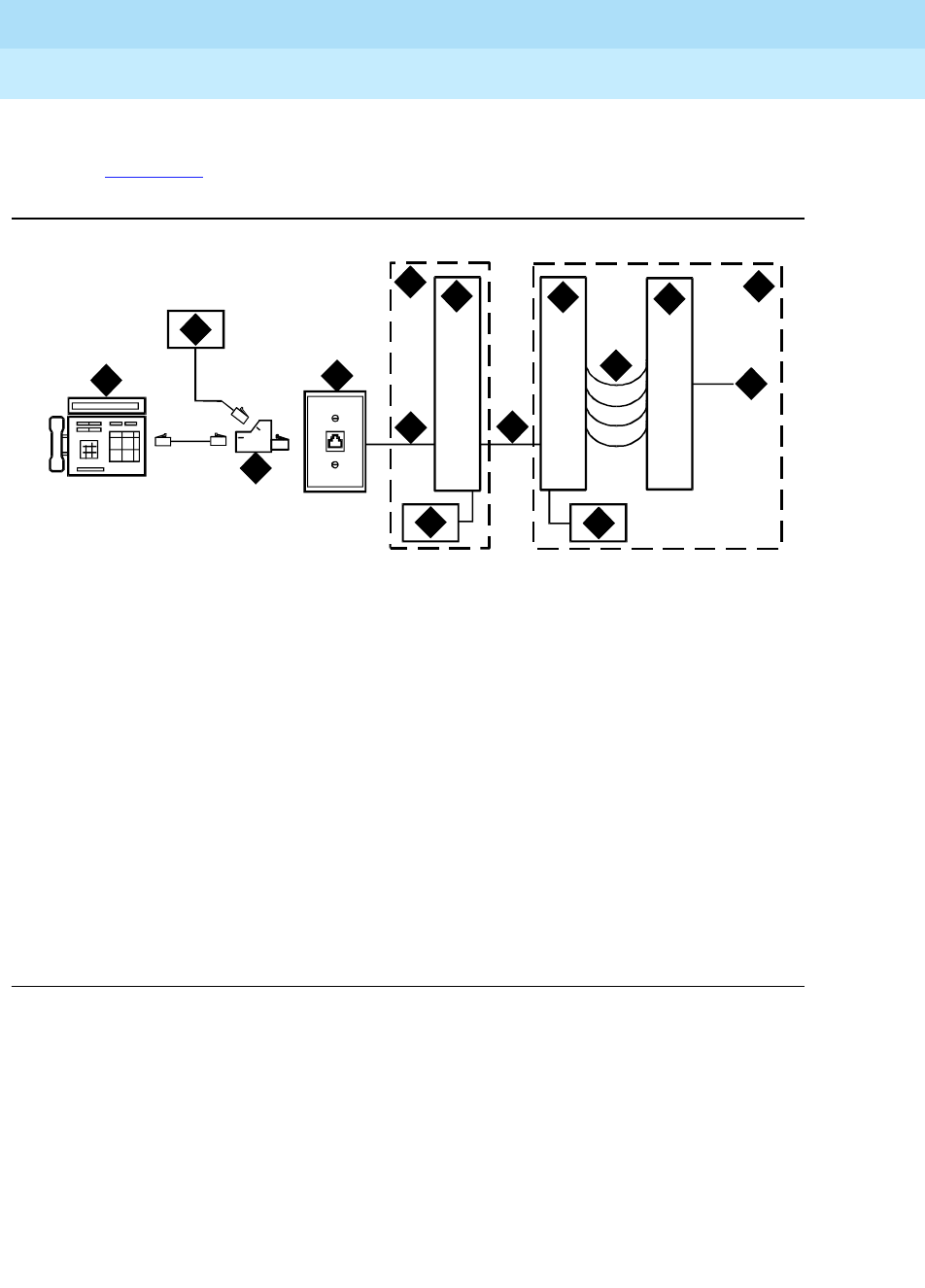
Figure 1-32 shows typical connection locations for adjunct power.
Figure 1-32. Example Adjunct Power Connections
Figure Notes
1. Typical display telephone
2. Individual power supply (Such as
1151A) (Not used if item 15 is used)
3. 400B2 adapter
4. Information outlet (modular jack)
5. 4-pair D-Inside Wire (DIW) cable
6. Satellite site or adapter location
7. 25-pair D-Inside Wire (DIW) cable
8. Station side of MDF
9. 100P6A patch cord or jumpers
10. System side of MDF
11. 25-pair cable to digital line circuit
pack
12. Equipment room
13. Satellite location
14. Bulk power supply (Such as
1145B). Install at satellite location
or equipment room (not both).
adjunctRPY 012098
1
2
3
4
5
6
7
8
9
10
11
12
13
14
15