


DEFINITY Enterprise Communications Server Release 6
Installation and Test for Compact Modular Cabinets
555-230-128
Issue 3
May 1998
Install and Cable the Cabinets
Page 1-91Install Emergency Transfer Unit and Associated Telephones
1
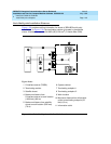
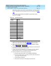
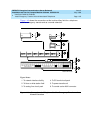
switches are used for each of the 5 circuits; switches 1 and 2 are used for
circuit 1, switches 3 and 4 are used for circuit 2, and so forth. See Ta b l e
1-16.
For loop start, set the switches to the left. For ground start, set the
switches to the right.
.
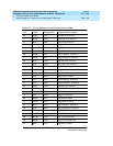
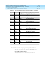
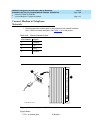
4. Connect a 25-pair cable between the male RJ21 25-pair connector on the
808A and the yellow field on the MDF. Table 1-17
shows the pinouts.
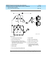
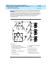
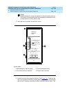
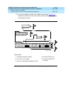
5. Make cross-connections for each emergency trunk/emergency station
pair. See Figure 1-42
and Figure 1-43.
6. On the trunk identification label at the bottom of the panel, record the trunk
line, extension, and location for each circuit.
7. To each voice terminal designated as an emergency terminal, attach a
label identifying it as such. The labels are provided with the unit.
8. Check the system for normal operation as follows:
a. Place the test switch (switch 12) in NORMAL OPERATION.
b. Ensure the power supply is providing -48 VDC at 80 mA maximum.
The power LED should be ON.
c. Check wiring connections.
d. Verify there is dial tone on all emergency transfer sets.
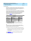
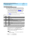
Table 1-16. Trunk/Test Switches
Switch
Number
Circuit
Number
11
21
32
42
53
63
74
84
95
10 5
11 Not Used
12 Test Switch